


Tutto sui PLC: la CPU
A practical engineering guide to PLC CPU operation, from deterministic scan cycles and I/O image tables to memory, communications, diagnostics, redundancy, processor sizing, and reliable system...

Designed to execute synchronized multi-axis control within a single space-saving envelope, the Mitsubishi Electric MR-J4W2-44B is a dual-axis digital AC servo amplifier operating on the MELSERVO-J4 platform. By consolidating control electronics for two independent 0.4 kW axes, this unit significantly reduces control panel footprints, optimizes power distribution, and streamlines network routing. The integration of high-speed SSCNET III/H optical fiber communications enables high-resolution motion synchronization with negligible electromagnetic interference, making it an ideal choice for high-speed, multi-axis automated assemblies.
| Manufacturer | Mitsubishi Electric |
| Model Number | MR-J4W2-44B |
| Series Name | MELSERVO-J4 (MR-J4) |
| Controlled Axes | 2 Axes (Axis A and Axis B) |
| Rated Output Power | 0.4 kW per axis (Total 0.8 kW) |
| Communication Interface | SSCNET III/H (Optical connection) |
| Main Circuit Power Supply | 3-phase 200 to 240 VAC, 50/60 Hz |
| Control Circuit Power Supply | 1-phase 200 to 240 VAC, 50/60 Hz |
| Encoder Compatibility | 22-bit absolute/incremental systems |
| Cooling Method | Natural cooling |
| Ambient Operating Temperature | 0 to 55 degC (non-freezing) |
| Dimensions (H x W x D) | 195 mm x 60 mm x 168 mm |
| Net Weight | 1.4 kg |
| Shipping Weight (Calculated) | 3.5 kg |
| Terminal / Connector Code | Functional Assignment |
|---|---|
| L1 / L2 / L3 | Main circuit power supply input (200-240 VAC) |
| L11 / L21 | Control circuit power supply input |
| U / V / W (Axis A) | Servo motor output terminals for Axis A |
| U / V / W (Axis B) | Servo motor output terminals for Axis B |
| CN1A / CN1B | SSCNET III/H optical fiber loop connectors (In/Out) |
| CN2A / CN2B | Encoder connection interfaces for Axis A / Axis B |
| CN8 | Functional safety signal connector (STO) |
The MR-J4W2 series is designed as the primary platform for multi-axis configurations within the MR-J4 ecosystem. Note that when migrating legacy MR-J3W units to the MR-J4W2 configuration, parameter translation within the programming suite (such as GX Works2 or GX Works3) is required. While physical mounting footprints differ slightly from single-axis units, the space gains from eliminating independent control power cabling easily justify the transition.
Because both Axis A and Axis B share a common internal DC bus, regenerative energy from decelerating one axis is naturally utilized by the second motoring axis. However, if both axes undergo simultaneous high-inertia deceleration, the regenerative capacity can quickly saturate the internal capacitor, triggering an Overvoltage (AL.33) fault. For operations with continuous regenerative cycles or high load inertia, always calculate total system regeneration requirements and connect an appropriately sized external regeneration resistor across the L+ and L- terminals.
When laying the SSCNET III/H optical fiber cables (MR-J3BUS_M), do not violate the minimum bend radius of 25 mm. Sharp bends or excessive zip-tie tension on the fiber optic routing will attenuate the light signal, leading to random line failures (AL.37) or communication errors (AL.E6). Always cap unused optical ports on the amplifier to prevent dust and humidity contamination of the optical transceiver lens.
CRITICAL WARNING:
Risk of electric shock and residual charge discharge. Always disconnect the main circuit and control circuit power supplies before beginning physical installation or wiring. Wait at least 15 minutes after power-down for the internal charge lamps on the front face of the amplifier to completely extinguish before handling cable connections.
Global Express Shipping
Returns & Warranty


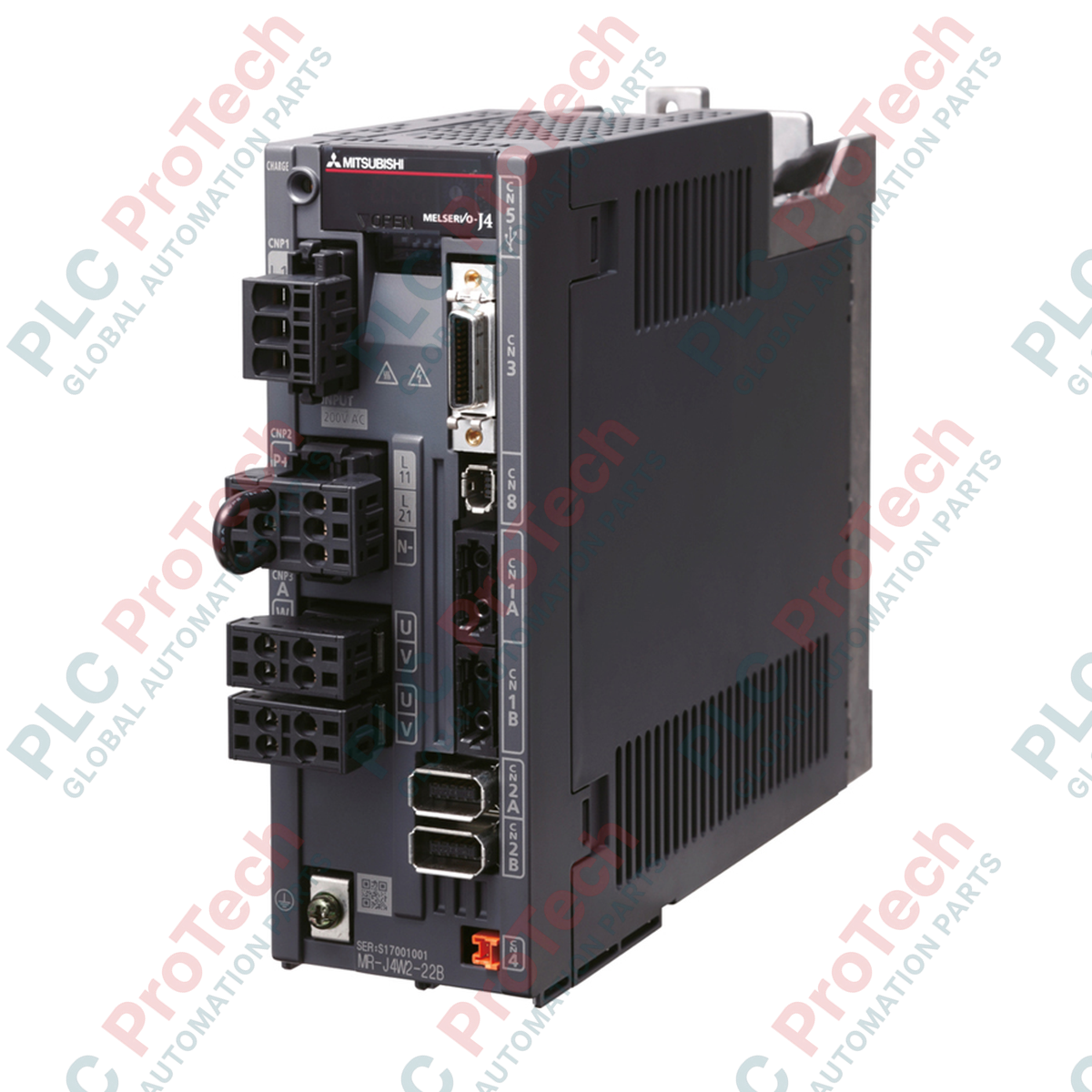
Manufacturer: Mitsubishi Electric
Product No.: MR-J4W2-44B
Country of origin:United States
Product Type: Servo Amplifiers
Payment: T/T, Western Union
Weight: 1400g
Dimensions: 195 mm x 60 mm x 168 mm
Shipping port: Xiamen
Warranty: 12 months
Designed to execute synchronized multi-axis control within a single space-saving envelope, the Mitsubishi Electric MR-J4W2-44B is a dual-axis digital AC servo amplifier operating on the MELSERVO-J4 platform. By consolidating control electronics for two independent 0.4 kW axes, this unit significantly reduces control panel footprints, optimizes power distribution, and streamlines network routing. The integration of high-speed SSCNET III/H optical fiber communications enables high-resolution motion synchronization with negligible electromagnetic interference, making it an ideal choice for high-speed, multi-axis automated assemblies.
| Manufacturer | Mitsubishi Electric |
| Model Number | MR-J4W2-44B |
| Series Name | MELSERVO-J4 (MR-J4) |
| Controlled Axes | 2 Axes (Axis A and Axis B) |
| Rated Output Power | 0.4 kW per axis (Total 0.8 kW) |
| Communication Interface | SSCNET III/H (Optical connection) |
| Main Circuit Power Supply | 3-phase 200 to 240 VAC, 50/60 Hz |
| Control Circuit Power Supply | 1-phase 200 to 240 VAC, 50/60 Hz |
| Encoder Compatibility | 22-bit absolute/incremental systems |
| Cooling Method | Natural cooling |
| Ambient Operating Temperature | 0 to 55 degC (non-freezing) |
| Dimensions (H x W x D) | 195 mm x 60 mm x 168 mm |
| Net Weight | 1.4 kg |
| Shipping Weight (Calculated) | 3.5 kg |
| Terminal / Connector Code | Functional Assignment |
|---|---|
| L1 / L2 / L3 | Main circuit power supply input (200-240 VAC) |
| L11 / L21 | Control circuit power supply input |
| U / V / W (Axis A) | Servo motor output terminals for Axis A |
| U / V / W (Axis B) | Servo motor output terminals for Axis B |
| CN1A / CN1B | SSCNET III/H optical fiber loop connectors (In/Out) |
| CN2A / CN2B | Encoder connection interfaces for Axis A / Axis B |
| CN8 | Functional safety signal connector (STO) |
The MR-J4W2 series is designed as the primary platform for multi-axis configurations within the MR-J4 ecosystem. Note that when migrating legacy MR-J3W units to the MR-J4W2 configuration, parameter translation within the programming suite (such as GX Works2 or GX Works3) is required. While physical mounting footprints differ slightly from single-axis units, the space gains from eliminating independent control power cabling easily justify the transition.
Because both Axis A and Axis B share a common internal DC bus, regenerative energy from decelerating one axis is naturally utilized by the second motoring axis. However, if both axes undergo simultaneous high-inertia deceleration, the regenerative capacity can quickly saturate the internal capacitor, triggering an Overvoltage (AL.33) fault. For operations with continuous regenerative cycles or high load inertia, always calculate total system regeneration requirements and connect an appropriately sized external regeneration resistor across the L+ and L- terminals.
When laying the SSCNET III/H optical fiber cables (MR-J3BUS_M), do not violate the minimum bend radius of 25 mm. Sharp bends or excessive zip-tie tension on the fiber optic routing will attenuate the light signal, leading to random line failures (AL.37) or communication errors (AL.E6). Always cap unused optical ports on the amplifier to prevent dust and humidity contamination of the optical transceiver lens.
CRITICAL WARNING:
Risk of electric shock and residual charge discharge. Always disconnect the main circuit and control circuit power supplies before beginning physical installation or wiring. Wait at least 15 minutes after power-down for the internal charge lamps on the front face of the amplifier to completely extinguish before handling cable connections.
Global Express Shipping
Returns & Warranty
Orders are processed and delivered Monday-Friday (excluding public holidays).
For full eligibility, restocking fees, and international return details, please view our official Refund & Return Policy .
| Country of origin |
United States
|

A practical engineering guide to PLC CPU operation, from deterministic scan cycles and I/O image tables to memory, communications, diagnostics, redundancy, processor sizing, and reliable system...

Sostituire un 1756-L73 non significa automaticamente aggiornare il firmware. Questa guida confronta le versioni 19.013, 21.011 e 31.011, concentrandosi sulla compatibilità dei progetti, sulle...

Implementa un circuito luminoso XOR con 3 interruttori SPST in LogixPro o RSLogix 500 utilizzando un bit di relè interno. Include tabelle della verità, equazioni booleane e verifica.

Integra Allen-Bradley CompactLogix, Caterpillar ATS e generatori nel DCS DeltaV tramite Modbus RTU. Include i gateway ProSoft MVI69-MCM e Miille DIN266.

L’istruzione ONS si attiva, ma la bobina OTE non rimane mai eccitata in Studio 5000 perché il one-shot è vero solo per una scansione. Usa OTL/OTU oppure una logica di autoritenuta.

Configura i servoazionamenti Allen-Bradley Kinetix 5500 su EtherNet/IP. Include CIP Sync, la temporizzazione IEEE 1588 V2, la selezione degli switch Stratix, la topologia DLR e l’HMI.