Pepperl + Fuchs

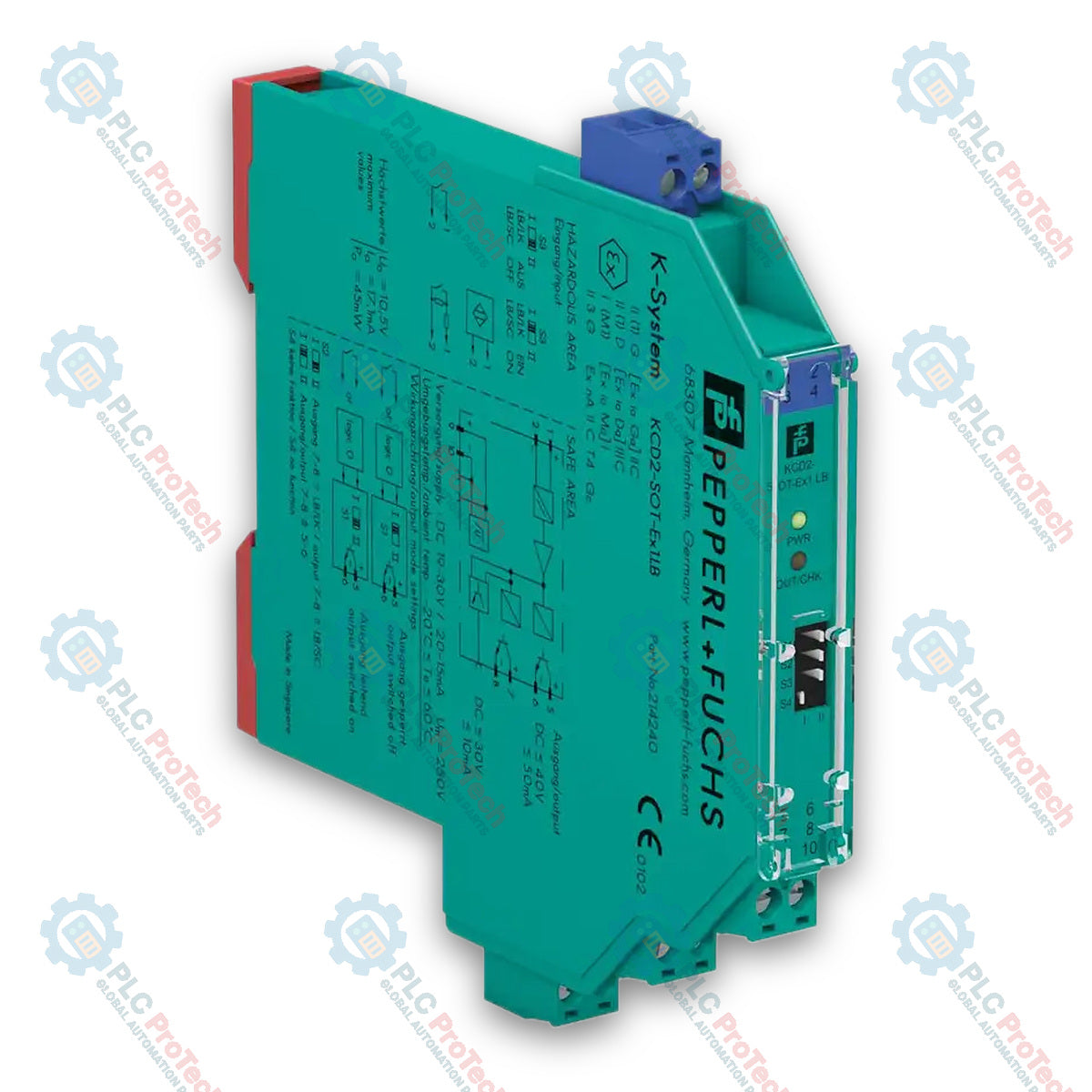
Pepperl+Fuchs 214240 KCD2-SOT-Ex1.LB Switch Amplifier

SKU KCD2-SOT-Ex1.LB

Disponibile
  • 12-month warranty
  • Free returns within 30 days
  • Manufacturer: Pepperl + Fuchs
  • Product No.: KCD2-SOT-Ex1.LB
  • Origin United States
  • Product Type: Isolating Switch Amplifiers
  • Payment: T/T, Western Union
  • Weight: 0.1 kg
  • Dimensions: 12.5 x 119 x 114 mm (W x H x D)
  • Shipping port: Xiamen
  • Warranty: 12 months

Tags

Product Documentation

Technical Datasheet (PDF) Complete specifications and technical drawings.

Technical Datasheet

Pepperl+Fuchs 214240 KCD2-SOT-Ex1.LB Switch Amplifier

Quantità

Product Description

Description

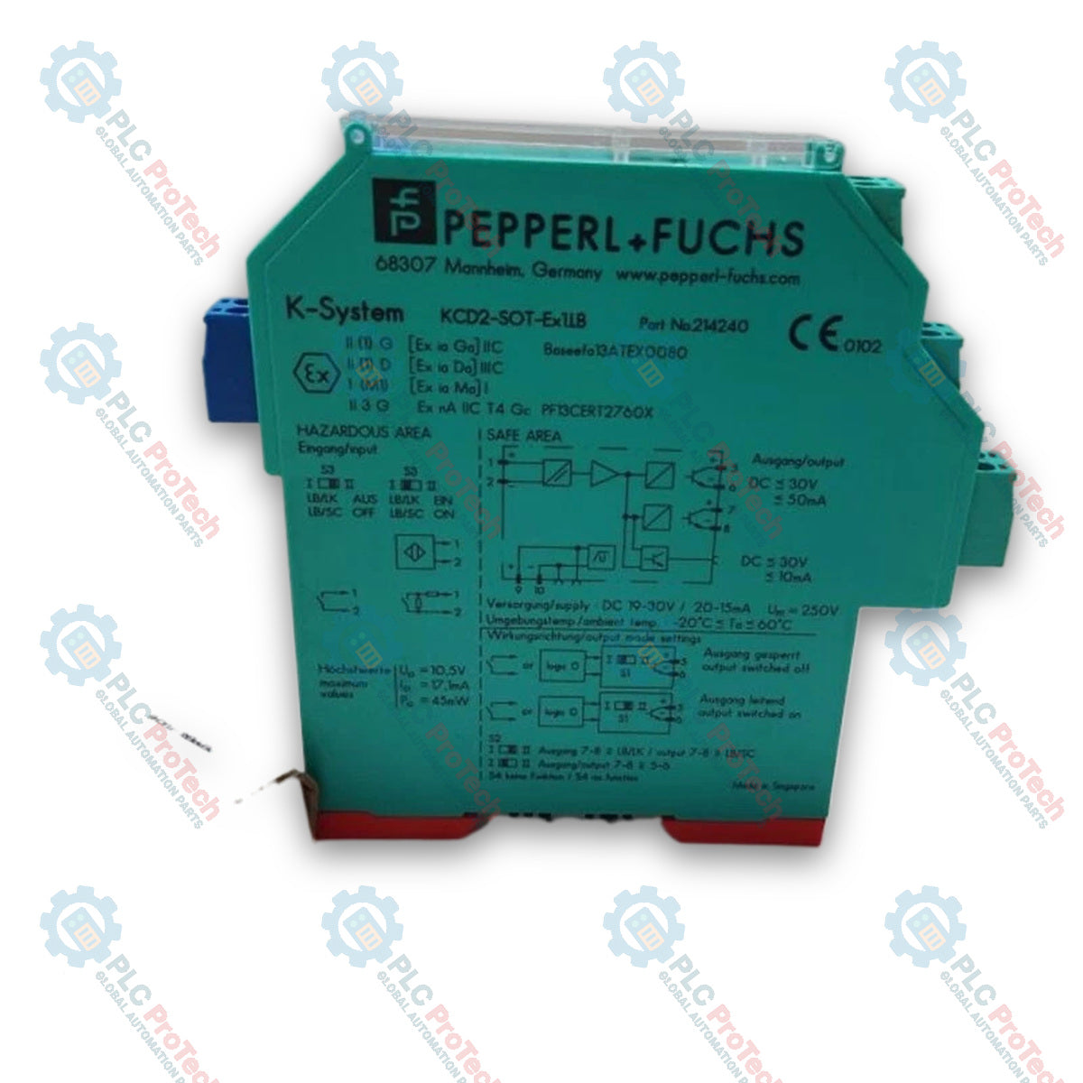
The Pepperl+Fuchs KCD2-SOT-Ex1.LB is a 1-channel isolated barrier designed for intrinsic safety applications to transfer digital signals from hazardous areas to safe areas. This device features a single field-side digital input that controls two passive transistor outputs on the control side. Configurable via DIP switches, the unit can function as a signal splitter (1 input and 2 outputs) or assign its second transistor output as an error indicator. The KCD2-SOT-Ex1.LB switch amplifier supports line fault detection (LFD) for monitoring lead breakage and short circuits, and processes signals from dry contacts or NAMUR sensors according to EN 60947-5-6.

Features

  • 1-channel isolated barrier for intrinsic safety applications
  • 24 V DC supply via removable screw terminals or Power Rail
  • Dry contact or NAMUR sensor input
  • 2 passive transistor outputs with reversible mode of operation
  • Usable as a signal splitter (1 input to 2 outputs)
  • Line fault detection (LFD) for lead breakage and short-circuit monitoring
  • Collective error message output via Power Rail
  • Front-accessible DIP switches for operational mode and fault detection configuration
  • Compact 12.5 mm housing width for DIN mounting rail installation
  • Up to SIL 2 (SC 3) safety evaluation according to IEC/EN 61508

Applications

  • Intrinsic safety signal isolation and processing in hazardous areas
  • Signal splitting from a single field sensor to multiple control devices
  • Interface conversion for NAMUR proximity sensors and discrete dry contact switches
  • Status monitoring and line fault detection in DCS, SIS, and PLC automation loops

Technical Specifications

Parameter Specification
Manufacturer Pepperl+Fuchs
Model KCD2-SOT-Ex1.LB
Order Number 214240
Signal Type Digital Input
Safety Integrity Level (SIL) SIL 2 (Systematic Capability SC 3)
Rated Voltage (Ur) 19 ... 30 V DC
Ripple <= 10%
Rated Current (Ir) 20 ... 15 mA
Power Dissipation <= 700 mW
Field Side Input Terminals 1+, 2- (NAMUR acc. to EN 60947-5-6)
Open Circuit Voltage / Short-Circuit Current approx. 10 V DC / approx. 8 mA
Switching Point / Hysteresis 1.2 ... 2.1 mA / approx. 0.2 mA
Line Fault Detection Breakage I <= 0.1 mA, Short-circuit I >= 6.5 mA
Pulse / Pause Ratio min. 100 us / min. 100 us
Control Side Output Output I: terminals 5+, 6-; Output II: terminals 7+, 8-
Output Type Passive Transistor
Output Rated Voltage (Ur) 30 V DC
Output Rated Current 50 mA
Response Time <= 200 us
Signal Level 1-signal: (external voltage) - 3 V max. for 50 mA; 0-signal: off-state current <= 10 uA
Switching Frequency <= 5 kHz
Galvanic Isolation (Input/Output, Input/Power) Reinforced insulation acc. to EN 50178, rated voltage 300 Veff
Galvanic Isolation (Output/Power, Output/Output) Basic insulation acc. to EN 50178, rated voltage 50 Veff
Safe Electrical Isolation (Hazardous to Safe) Acc. to IEC/EN 60079-11, voltage peak value 375 V
Ambient Temperature -20 ... 60 degC (-4 ... 140 degF), extended up to 70 degC (158 degF)
Degree of Protection IP20
Mounting On 35 mm DIN mounting rail acc. to EN 60715:2001
Connection Type Screw terminals
Mass approx. 100 g
Dimensions (W x H x D) 12.5 x 119 x 114 mm (0.5 x 4.7 x 4.5 inch), housing type A2

Connections/Interfaces

Connector Pin Function
1+ Field Input + (Hazardous Area)
2- Field Input - (Hazardous Area)
5+ Output I Transistor +
6- Output I Transistor -
7+ Output II Transistor +
8- Output II Transistor -
9+ Supply Voltage 24 V DC +
10- Supply Voltage 24 V DC -
Power Rail Supply Voltage 24 V DC / Collective Error Output

Installation Guidelines

  • DIN Rail Mounting: Snap the module onto a 35 mm DIN mounting rail complying with EN 60715:2001.
  • Wiring Requirements: Connect hazardous area field wiring to the top blue removable terminal block (terminals 1+, 2-). Connect safe area output and power wiring to the bottom green removable terminal blocks.
  • Power Supply: Supply 19 ... 30 V DC via screw terminals 9+ and 10- or directly through the Power Rail system.
  • Configuration: Set front DIP switches (S1, S2, S3) to select output active mode, assign output II function, and enable or disable line fault detection.
  • Hazardous Area Precautions: Ensure intrinsic safety parameters (Uo = 10.5 V, Io = 17.1 mA, Po = 45 mW) match field device specifications and maximum safe voltage (Um = 253 V AC) limits are respected.

Compliance and Certifications

  • Safety Integrity Level: SIL 2, Systematic Capability SC 3 acc. to IEC/EN 61508
  • ATEX Certification: BASEEFA 13 ATEX 0080, CML 19 ATEX 4410 X
  • ATEX Marking: II (1)G [Ex ia Ga] IIC, II (1)D [Ex ia Da] IIIC, I (M1) [Ex ia Ma] I, II 3G Ex ec IIC T4 Gc
  • IECEx Certification: IECEx BAS 13.0046, IECEx CML 19.0147X
  • IECEx Marking: [Ex ia Ga] IIC, [Ex ia Da] IIIC, [Ex ia Ma] I, Ex ec IIC T4 Gc
  • UL Approval: Control drawing 116-0374 (cULus)
  • Electromagnetic Compatibility: Directive 2014/30/EU, EN 61326-1:2013, NE 21:2011
  • Protection Standards: IEC 60529:2001 (IP20), IEC 61010-1:2010
  • Input Standard: EN 60947-5-6:2000
Shipping &amp; Returns

Global Express Shipping

  • Standard Delivery: 4–6 business days via DHL, FedEx, and UPS.
  • Express Dispatch: Same-day dispatch for in-stock orders placed before 2:00 PM (GMT+8).
  • Worldwide Coverage: Serving over 150 countries.

Returns & Warranty

  • 30-Day Guarantee: Returns accepted for in-stock products in original, factory-sealed packaging.
  • 12-Month Warranty: Every industrial component is backed by our technical warranty.
FAQ
What power supply voltage does the device require for operation?
The module operates on a rated voltage range of 19 to 30 V DC via screw terminals or Power Rail.
Can output II be configured as a dedicated fault output?
Yes, setting DIP switch S2 configures the second passive transistor output to signal line fault indications.
What sensor types are compatible with the field input terminals?
The field input accepts standard NAMUR proximity sensors or dry contact switches located in hazardous areas.
How fast is the signal response time across the transistor outputs?
The passive transistor outputs feature a fast response time of less than or equal to 200 microseconds.
Reviews

KCD2-SOT-Ex1.LB

Stock &amp; lead time on request

Call
1 su 3

Pepperl+Fuchs 214240 KCD2-SOT-Ex1.LB Switch Amplifier

Only 10 item(s) left in stock
  • Manufacturer: Pepperl + Fuchs

  • Product No.: KCD2-SOT-Ex1.LB

  • Country of origin:United States

  • Product Type: Isolating Switch Amplifiers

  • Payment: T/T, Western Union

  • Weight: 100g

  • Dimensions: 12.5 x 119 x 114 mm (W x H x D)

  • Shipping port: Xiamen

  • Warranty: 12 months

Quantità
Visualizza dettagli completi

Product Description

Description

The Pepperl+Fuchs KCD2-SOT-Ex1.LB is a 1-channel isolated barrier designed for intrinsic safety applications to transfer digital signals from hazardous areas to safe areas. This device features a single field-side digital input that controls two passive transistor outputs on the control side. Configurable via DIP switches, the unit can function as a signal splitter (1 input and 2 outputs) or assign its second transistor output as an error indicator. The KCD2-SOT-Ex1.LB switch amplifier supports line fault detection (LFD) for monitoring lead breakage and short circuits, and processes signals from dry contacts or NAMUR sensors according to EN 60947-5-6.

Features

  • 1-channel isolated barrier for intrinsic safety applications
  • 24 V DC supply via removable screw terminals or Power Rail
  • Dry contact or NAMUR sensor input
  • 2 passive transistor outputs with reversible mode of operation
  • Usable as a signal splitter (1 input to 2 outputs)
  • Line fault detection (LFD) for lead breakage and short-circuit monitoring
  • Collective error message output via Power Rail
  • Front-accessible DIP switches for operational mode and fault detection configuration
  • Compact 12.5 mm housing width for DIN mounting rail installation
  • Up to SIL 2 (SC 3) safety evaluation according to IEC/EN 61508

Applications

  • Intrinsic safety signal isolation and processing in hazardous areas
  • Signal splitting from a single field sensor to multiple control devices
  • Interface conversion for NAMUR proximity sensors and discrete dry contact switches
  • Status monitoring and line fault detection in DCS, SIS, and PLC automation loops

Technical Specifications

Parameter Specification
Manufacturer Pepperl+Fuchs
Model KCD2-SOT-Ex1.LB
Order Number 214240
Signal Type Digital Input
Safety Integrity Level (SIL) SIL 2 (Systematic Capability SC 3)
Rated Voltage (Ur) 19 ... 30 V DC
Ripple <= 10%
Rated Current (Ir) 20 ... 15 mA
Power Dissipation <= 700 mW
Field Side Input Terminals 1+, 2- (NAMUR acc. to EN 60947-5-6)
Open Circuit Voltage / Short-Circuit Current approx. 10 V DC / approx. 8 mA
Switching Point / Hysteresis 1.2 ... 2.1 mA / approx. 0.2 mA
Line Fault Detection Breakage I <= 0.1 mA, Short-circuit I >= 6.5 mA
Pulse / Pause Ratio min. 100 us / min. 100 us
Control Side Output Output I: terminals 5+, 6-; Output II: terminals 7+, 8-
Output Type Passive Transistor
Output Rated Voltage (Ur) 30 V DC
Output Rated Current 50 mA
Response Time <= 200 us
Signal Level 1-signal: (external voltage) - 3 V max. for 50 mA; 0-signal: off-state current <= 10 uA
Switching Frequency <= 5 kHz
Galvanic Isolation (Input/Output, Input/Power) Reinforced insulation acc. to EN 50178, rated voltage 300 Veff
Galvanic Isolation (Output/Power, Output/Output) Basic insulation acc. to EN 50178, rated voltage 50 Veff
Safe Electrical Isolation (Hazardous to Safe) Acc. to IEC/EN 60079-11, voltage peak value 375 V
Ambient Temperature -20 ... 60 degC (-4 ... 140 degF), extended up to 70 degC (158 degF)
Degree of Protection IP20
Mounting On 35 mm DIN mounting rail acc. to EN 60715:2001
Connection Type Screw terminals
Mass approx. 100 g
Dimensions (W x H x D) 12.5 x 119 x 114 mm (0.5 x 4.7 x 4.5 inch), housing type A2

Connections/Interfaces

Connector Pin Function
1+ Field Input + (Hazardous Area)
2- Field Input - (Hazardous Area)
5+ Output I Transistor +
6- Output I Transistor -
7+ Output II Transistor +
8- Output II Transistor -
9+ Supply Voltage 24 V DC +
10- Supply Voltage 24 V DC -
Power Rail Supply Voltage 24 V DC / Collective Error Output

Installation Guidelines

  • DIN Rail Mounting: Snap the module onto a 35 mm DIN mounting rail complying with EN 60715:2001.
  • Wiring Requirements: Connect hazardous area field wiring to the top blue removable terminal block (terminals 1+, 2-). Connect safe area output and power wiring to the bottom green removable terminal blocks.
  • Power Supply: Supply 19 ... 30 V DC via screw terminals 9+ and 10- or directly through the Power Rail system.
  • Configuration: Set front DIP switches (S1, S2, S3) to select output active mode, assign output II function, and enable or disable line fault detection.
  • Hazardous Area Precautions: Ensure intrinsic safety parameters (Uo = 10.5 V, Io = 17.1 mA, Po = 45 mW) match field device specifications and maximum safe voltage (Um = 253 V AC) limits are respected.

Compliance and Certifications

  • Safety Integrity Level: SIL 2, Systematic Capability SC 3 acc. to IEC/EN 61508
  • ATEX Certification: BASEEFA 13 ATEX 0080, CML 19 ATEX 4410 X
  • ATEX Marking: II (1)G [Ex ia Ga] IIC, II (1)D [Ex ia Da] IIIC, I (M1) [Ex ia Ma] I, II 3G Ex ec IIC T4 Gc
  • IECEx Certification: IECEx BAS 13.0046, IECEx CML 19.0147X
  • IECEx Marking: [Ex ia Ga] IIC, [Ex ia Da] IIIC, [Ex ia Ma] I, Ex ec IIC T4 Gc
  • UL Approval: Control drawing 116-0374 (cULus)
  • Electromagnetic Compatibility: Directive 2014/30/EU, EN 61326-1:2013, NE 21:2011
  • Protection Standards: IEC 60529:2001 (IP20), IEC 61010-1:2010
  • Input Standard: EN 60947-5-6:2000

Product Documentation

Technical Datasheet (PDF) Complete specifications and technical drawings.

Technical Datasheet

Pepperl+Fuchs 214240 KCD2-SOT-Ex1.LB Switch Amplifier

What power supply voltage does the device require for operation?

The module operates on a rated voltage range of 19 to 30 V DC via screw terminals or Power Rail.

Can output II be configured as a dedicated fault output?

Yes, setting DIP switch S2 configures the second passive transistor output to signal line fault indications.

What sensor types are compatible with the field input terminals?

The field input accepts standard NAMUR proximity sensors or dry contact switches located in hazardous areas.

How fast is the signal response time across the transistor outputs?

The passive transistor outputs feature a fast response time of less than or equal to 200 microseconds.

Global Express Shipping

  • Standard Delivery: 4-6 Business Days via DHL, FedEx, and UPS.
  • Express Dispatch: Same-day dispatch for in-stock orders placed before 2:00 PM (GMT+8).
  • Worldwide Coverage: Serving over 150 countries, including rapid delivery to Saudi Arabia and UAE.

Returns & Warranty

  • 30-Day Guarantee: Returns accepted for in-stock products in original, factory-sealed packaging.
  • 12-Month Warranty: Every industrial component is backed by our professional technical warranty.

Orders are processed and delivered Monday-Friday (excluding public holidays).


For full eligibility, restocking fees, and international return details, please view our official Refund & Return Policy .

TECHNICAL SPECIFICATIONS

Country of origin
United States

Technical knowledge

Tutto sui PLC: la CPU

A practical engineering guide to PLC CPU operation, from deterministic scan cycles and I/O image tables to memory, communications, diagnostics, redundancy, processor sizing, and reliable system...

Guida all’aggiornamento del firmware 1756-L73: scelta tra v19 e v21/v31

Sostituire un 1756-L73 non significa automaticamente aggiornare il firmware. Questa guida confronta le versioni 19.013, 21.011 e 31.011, concentrandosi sulla compatibilità dei progetti, sulle...

Implementazione della logica a scala XOR con 3 interruttori e bit interno

Implementa un circuito luminoso XOR con 3 interruttori SPST in LogixPro o RSLogix 500 utilizzando un bit di relè interno. Include tabelle della verità, equazioni booleane e verifica.

Creazione di una rete Modbus RTU con CompactLogix e DeltaV

Integra Allen-Bradley CompactLogix, Caterpillar ATS e generatori nel DCS DeltaV tramite Modbus RTU. Include i gateway ProSoft MVI69-MCM e Miille DIN266.

Istruzione ONS che non attiva l’OTE nella logica ladder di Studio 5000

L’istruzione ONS si attiva, ma la bobina OTE non rimane mai eccitata in Studio 5000 perché il one-shot è vero solo per una scansione. Usa OTL/OTU oppure una logica di autoritenuta.

Requisiti e topologia dello switch di rete EtherNet/IP Kinetix 5500

Configura i servoazionamenti Allen-Bradley Kinetix 5500 su EtherNet/IP. Include CIP Sync, la temporizzazione IEEE 1588 V2, la selezione degli switch Stratix, la topologia DLR e l’HMI.