Description
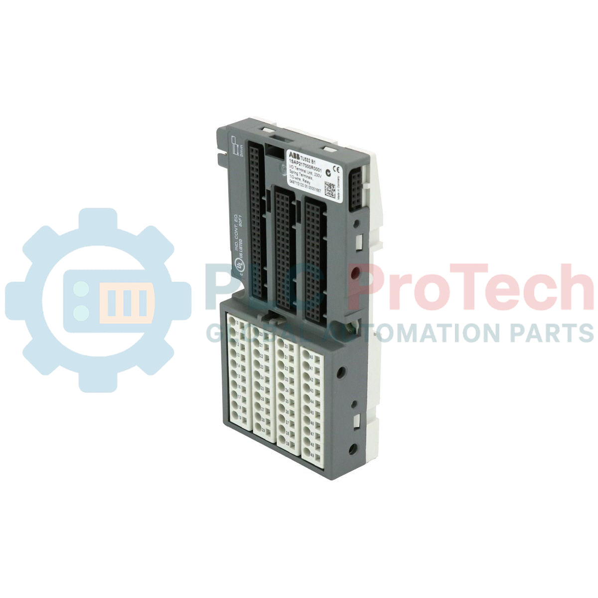
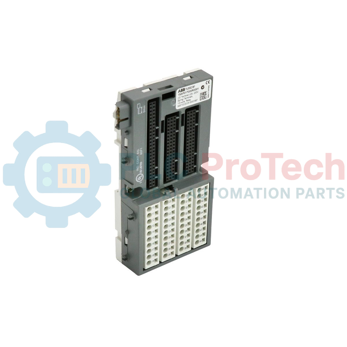
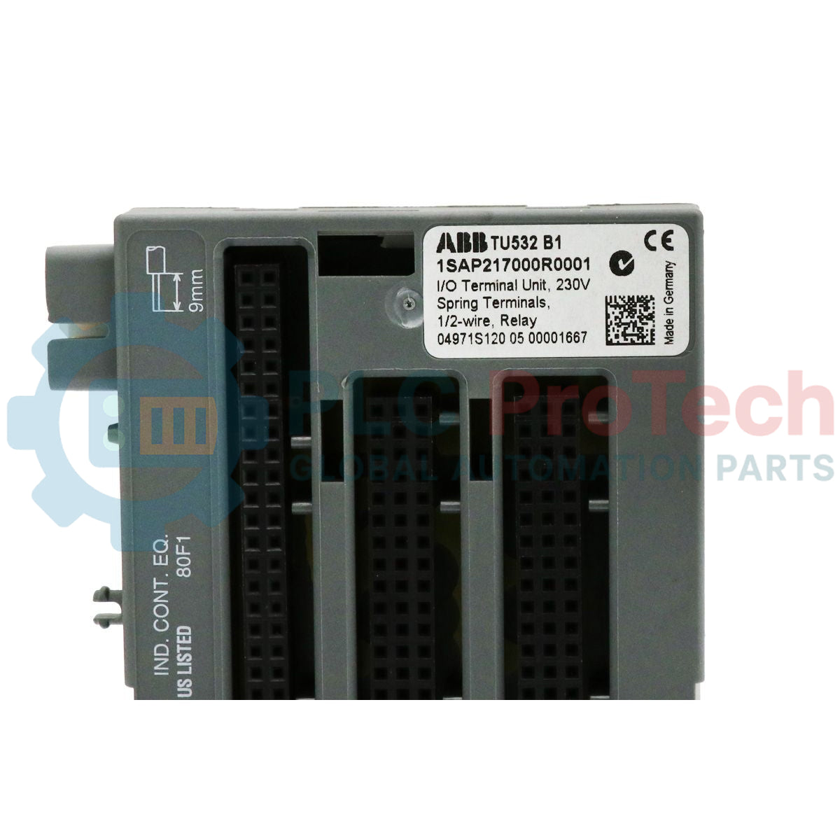
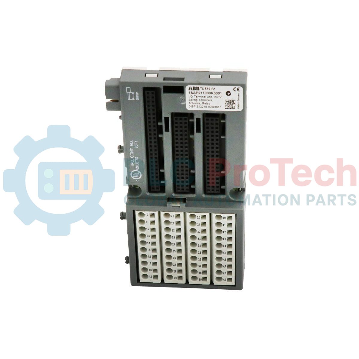
Designed to integrate high-voltage modules within the control rack architecture, the ABB 1SAP217000R0001 provides a robust mechanical and electrical connection interface for the Advant AC500 PLC platform. This TU532 unit is configured with vibration-resistant spring terminals specifically optimized for 230 VAC and relay output modules. It serves as an essential deployment base, routing field wiring securely to the internal backplane bus while allowing hot-swapping or field replacement of active electronic I/O modules without disturbing field termination lines.
Features
-
High-Voltage Isolation: Specifically rated and safety-spaced for 230 VAC applications and high-capacity relay interfaces.
-
Spring-Clamp Termination: Rapid, maintenance-free field connection technology that maintains constant clamping pressure, preventing loose connections due to thermal cycling or vibration.
-
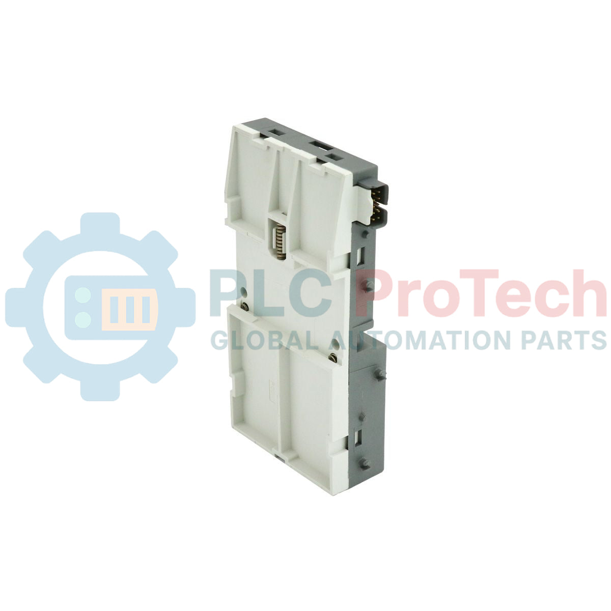
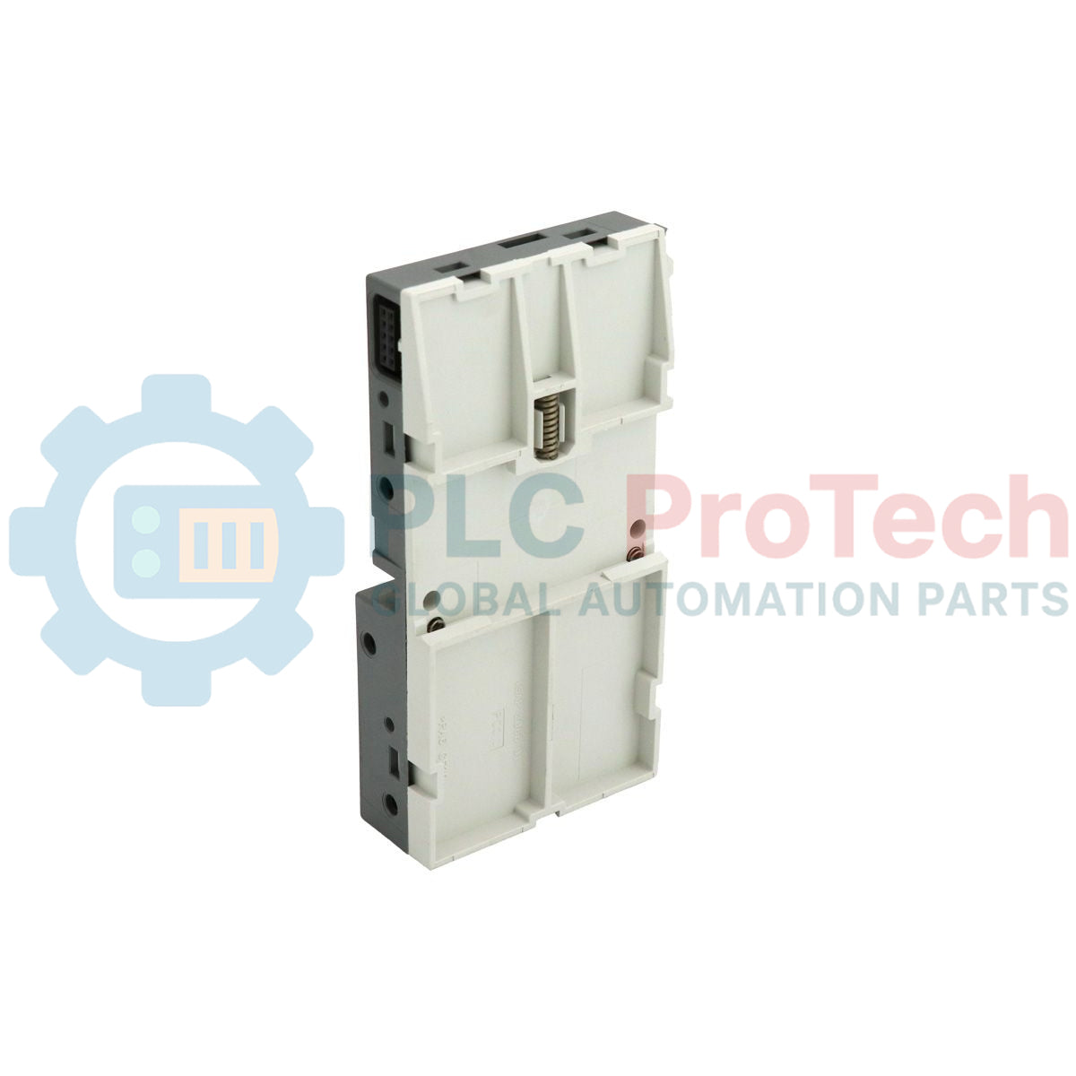
System Integration: Designed for seamless backplane and electrical mounting with S500 distributed I/O systems.
-
Auxiliary Supply Support: Accommodates 24 VDC auxiliary power routing for operational module circuitry.
-
Compact Profile: Minimal panel footprint maximizing vertical and horizontal packing density inside local control panels.
Applications
- Large-scale distributed automation systems requiring localized 230 VAC digital signaling.
- Industrial motor control centers and mechanical interface panels using AC500 relay outputs.
- Substation and heavy utility process controls where high-voltage switching isolation is mandatory.
Technical Specifications
| Manufacturer |
ABB |
| Model Series |
Advant AC500 / S500 |
| Extended Product Type |
TU532 |
| Article Number (SKU) |
1SAP217000R0001 |
| Terminal Type |
Spring-clamp terminals |
| Voltage Capacity |
230 VAC / Relay Module Compatible |
| Auxiliary Supply Voltage |
24 VDC |
| Degree of Protection |
IP20 |
| Operating Temperature |
0 to +60 degC |
| Storage Temperature |
-40 to +70 degC |
| Net Dimensions (W x H x D) |
28 x 135 x 67.5 mm |
| Net Weight |
0.164 kg |
| Gross Shipping Weight |
0.194 kg |
| Package Dimensions |
147 x 78 x 40 mm |
Empirical Engineering Insights
Alternative Models & Compatibility: The TU532 terminal unit is configured explicitly for high-voltage 230 VAC and relay-isolated cards. Do not substitute this unit with the TU512 or TU516 terminal bases, which are engineered for low-voltage 24 VDC signal modules. Doing so violates dielectric separation spacing and voids the hazardous location ratings of the S500 system architecture.
Application Pitfalls & Engineering Notes: When switching inductive AC loads (solenoids, contactor coils) through relay modules installed on the TU532, ensure external RC suppression elements are deployed across the contact terminals. Failing to suppress contact arcing can induce high-frequency EMI back into the local backplane, risking bus communication failures or unexpected state resets.
Commissioning & Wiring Tips: Stranded conductors inserted into the TU532 tension clamps require the use of properly crimped, insulated wire end ferrules. Raw, un-insulated stranded wire can easily experience splaying within the high-density terminal housing, risking phase-to-phase shorts on 230 VAC lines or grounding errors.
Installation Guidelines
CRITICAL WARNING: Isolate all field 230 VAC lines and auxiliary 24 VDC control power sources prior to terminal unit installation, modification, or module insertion. Contact with active high-voltage connections can lead to fatal shock or permanent hardware destruction.
1
Align the upper hook of the TU532 terminal unit onto the top edge of a grounded 35 mm DIN rail.
2
Press the lower portion of the housing down firmly until the structural mounting latch snaps onto the rail.
3
Securely terminate the 230 VAC field lines and relay loops using a flat-bladed terminal screwdriver to actuate the spring-clamp mechanisms.
4
Verify routing and clearance of the 24 VDC auxiliary power supply connections before mounting the active I/O module onto the terminal unit interface.