Description
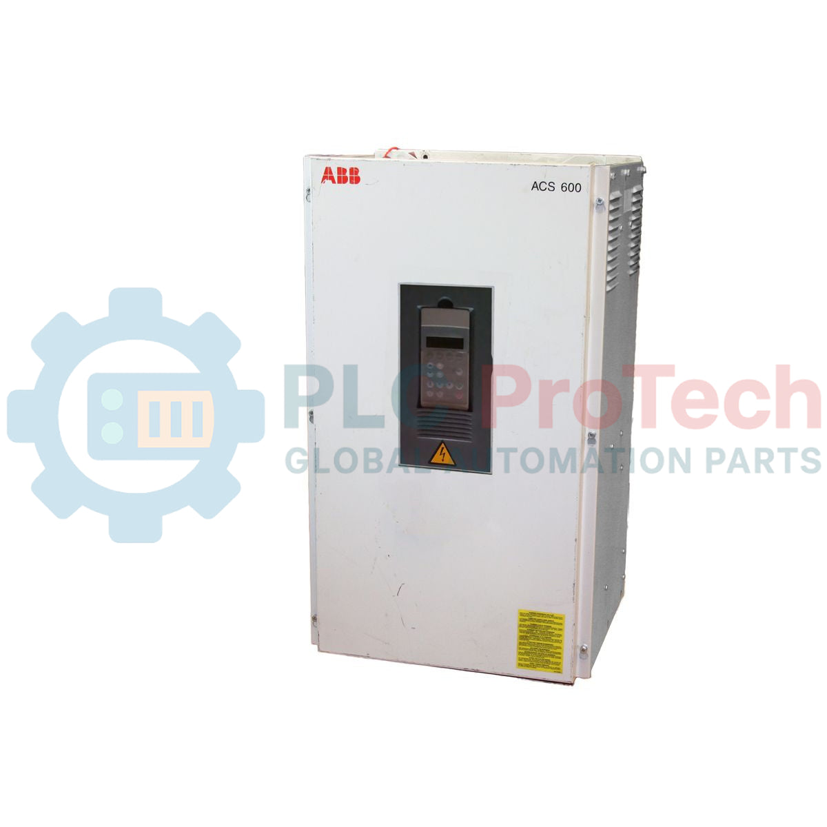
Optimizing heavy-duty motor control across demanding industrial architectures, the ABB ACS601-0100-3 is a high-performance three-phase AC frequency converter designed for precise speed and torque regulation of induction motors. Utilizing ABB's proprietary Direct Torque Control (DTC) platform, this frequency converter delivers rapid dynamic torque response without requiring encoder feedback in most standard applications. The robust physical design features a wall-mountable configuration, integrated line choke for input harmonics mitigation, and compatibility with various industrial communication adapters to ensure seamless system integration.
Features
-
Direct Torque Control (DTC): Provides motor control performance with exceptional torque response and speed accuracy.
-
Integrated Harmonics Mitigation: Built-in AC choke limits input line harmonics and protects the input rectifier stages.
-
Flexible Communications: Compatible with optional fieldbus modules for integration into PROFIBUS, Modbus, and EtherNet networks.
-
Robust IP21 Protection: Designed for standard industrial wall-mount installation environments.
-
Comprehensive Protection Matrix: Real-time monitoring for overcurrent, overvoltage, motor thermal overload, and earth leakage faults.
Applications
- Heavy-duty industrial centrifugal pumps and waste-water processing fans.
- Continuous material handling, heavy conveyors, and sorting systems.
- Extruder drives, industrial mixers, and high-torque agitators in chemical processing.
Technical Specifications
| Parameter |
Specification Value |
| Manufacturer |
ABB |
| Model Identifier |
ACS601-0100-3 |
| Product Series |
ACS 600 |
| Nominal Power Rating |
75 kW (100 HP) |
| Input Voltage Range |
380 V to 415 V AC, 3-phase |
| Nominal Output Current |
Approx. 140 A to 150 A (dependent on carrier frequency) |
| Input Frequency Range |
48 Hz to 63 Hz |
| Enclosure Rating |
IP21 (Standard Wall Mount) |
| Operating Temperature Range |
0 to 40 degC |
| Physical Dimensions |
175 cm x 58 cm x 79 cm |
| Net Weight |
88.00 kg |
| Commodity Code |
85044095 |
Connections and Interfaces
The terminal block configurations of the integrated NIOC-01 control board provide versatile, isolated control interfaces:
| Terminal / Connector Block |
Function and Assignment |
| X21 (Analog I/O) |
Supports 2 programmable differential analog inputs and 2 programmable analog outputs. |
| X22 (Digital Inputs) |
6 programmable digital inputs for start/stop, direction, and interlock commands. |
| X23 (Relay Outputs) |
3 programmable relay contact outputs for system status and fault signaling. |
| X25 (Internal Supply) |
Dedicated auxiliary +24 V DC power supply terminals for control logic. |
Alternative Models & Compatibility
When migrating legacy systems, note that the ACS601 (wall-mounted) differs physically from the ACS604 (cabinet-installed modules) and the ACS607 (pre-assembled drive cabinets). Main control board variations, such as the NAMC-11 or NAMC-51 boards, dictate firmware compatibility. Ensure that parameter databases and firmware releases match prior to field component replacement, as mismatching can trigger communication faults on the DDCS channel.
Application Pitfalls & Engineering Notes
Electrolytic Capacitor Aging: If this converter has been stored without electrical power for over two years, the DC bus capacitors must be reformed before applying full line voltage. Applying rapid mains voltage to unconditioned capacitors can lead to immediate hardware damage or DC overvoltage faults. Utilize a variable DC power supply to gradually reform the dielectric layers in accordance with ABB service manuals.
Commissioning & Wiring Tips
Always utilize symmetrical, shielded motor cabling to suppress common-mode high-frequency currents. Standard non-shielded cables can generate radio frequency emissions and high shaft voltages, accelerating motor bearing failure. Verify that the PE ground terminal connection is established with a minimum 360-degree shielding clamp at both the converter bracket and the motor frame to minimize electromagnetic interference.
Installation Guidelines
CRITICAL SAFETY WARNING
Ensure absolute isolation from mains electrical energy prior to opening the enclosure. High-voltage DC bus capacitors retain dangerous residual charge even after input power is disconnected. Wait a minimum of 5 minutes following isolation, and verify that the DC bus potential has discharged to less than 50 V DC using an appropriate multimeter before beginning work.
1
Mount the converter unit vertically onto a rigid, non-flammable surface. Ensure at least 300 mm of unobstructed cooling clearance above and below the internal fan intake/exhaust paths.
2
Route mains power input cables and motor-phase output cables through dedicated, separate metallic conduit passages to prevent electromagnetic coupling.
3
Secure all digital, analog, and communication control wiring within shielded cables. Connect the shield drain wires exclusively to the designated chassis grounding plates inside the drive.