Description
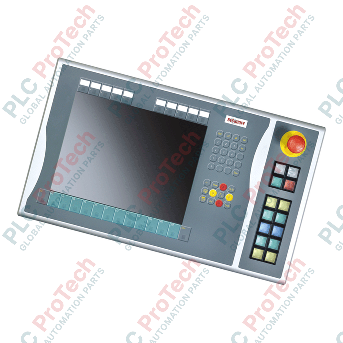
Designed for seamless physical integration alongside 15-inch control interfaces, the Beckhoff C9900-E701 provides supplementary tactile control elements for the CP6xxx and CP7xxx Control Panel and Panel PC series. This right-side mounted extension module bridges physical push-button operations with digital control bus networks, offering operators immediate, tactile feedback without utilizing screen real estate. Outfitted with heavy-duty Siemens Signum square 30 x 30 mm push-buttons and an independent Emergency Stop circuit, this assembly supports hybrid wiring structures to balance high-speed bus communication with fail-safe, hardware-interlocked emergency circuits.
Features
-
Optimized Compatibility: Purpose-built for mounting on the right-hand side of Beckhoff CP6x21-00xx and CP7x21-00xx 15-inch displays without integrated keyboards.
-
High-Tactile Interface: Equipped with 12 square 30 x 30 mm Siemens Signum push-button keys, complete with individual signal lamps.
-
Dual-Channel Safety Design: Incorporates 1 Siemens Signum emergency stop key designed for direct, hardwired safety loop integration.
-
Flexible Signal Routing: Primary normally-open (NO) contacts for all buttons route directly via CP-Link or USB, while a secondary terminal row provides direct-wiring paths for redundant, independent physical interlocking.
-
In-Field Customization: Insertable label plates beneath transparent push-button caps allow quick, application-specific functional labeling.
Applications
-
Heavy Industrial Machinery: Direct physical jog, homing, and cycle-start overrides adjacent to main visualization software.
-
Automotive Assembly Lines: Standardized operator consoles requiring dedicated hardware-interlocked E-stop functionality.
-
Process Plant Visualization: Panel-mount operator stations where software-only button actions pose potential operational delay risks.
Technical Specifications
| Specification Parameter |
Technical Value |
| Manufacturer |
Beckhoff Automation |
| Model Designation |
C9900-E701 |
| Compatible Panels |
CP6x21-00xx & CP7x21-00xx series (15-inch displays without keyboard) |
| Mounting Configuration |
Right-side mounting relative to display face |
| Operator Elements |
12 x push-buttons (Siemens Signum, 30 x 30 mm) with integrated signal lamps |
| Primary Contact Path |
|
Secondary Contact Path |
2nd Normally Open (NO) contact wired directly to physical terminal block row |
| Signal Lamp Control |
Transmitted exclusively via CP-Link or USB interface |
| Emergency Stop Element |
1 x Siemens Signum twist-to-release E-stop button (directly wireable) |
| Shipping Weight |
5.0 kg (11.0 lbs) |
| Package Dimensions (Calculated) |
450 x 200 x 150 mm (17.7 x 7.9 x 5.9 in) |
Connections and Interfaces
| Interface Type |
Connection Route & Signal Behavior |
| CP-Link / USB Bus Connection |
Transmits State 1 NO contact from each of the 12 buttons. Provides execution signals directly to the individual button feedback LEDs. |
| Direct Terminal Row |
Bypasses the communication controller, permitting dedicated copper wire connections for State 2 NO contacts. Useful for hardwired hardware safety feedback. |
| E-Stop Terminals |
Dedicated direct-wire connection blocks on the rear panel. Complete physical segregation from the digital CP-Link or USB communication logic. |
Empirical Engineering Insights
Alternative Models & Compatibility
The C9900-E701 is designed specifically for Beckhoff 15-inch display form factors without built-in keyboards. Integrating this extension with a model containing a physical keyboard is not mechanically possible due to spatial structural interference. When swapping panels during machine service phases, ensure that the communication bus setup (CP-Link versus direct USB) matches the control unit's existing interface cards, as logic mapping on the host Industrial PC will change accordingly.
Application Pitfalls & Engineering Notes
A common issue in field installations is routing safety-critical Emergency Stop signals through the USB or CP-Link bus rather than hardwiring them. Software-driven button monitoring is not rated for functional safety (SIL/PL) compliance. The red Emergency Stop mushroom cap must be direct-wired using copper connections through the dedicated rear terminal row to a certified safety controller or safety monitoring relay.
Commissioning & Wiring Tips
To protect the serial signaling over CP-Link/USB from electromagnetic interference, ensure that the connection cable running from the control panel to the main cabinet is fully shielded and routed separately from high-voltage motor cables or variable frequency drive (VFD) lines. In high-vibration environments, use strain reliefs at the direct terminal block row to prevent lead fatigue on the auxiliary NO contacts.
Installation Guidelines
CRITICAL WARNING
Isolate all electrical supply voltages to the Control Panel and terminal row circuits before starting mechanical mounting. Verify that all safety circuits are completely de-energized. Hardwired Emergency Stop lines must be validated for loop resistance and correct physical logic execution before restoring system operation.
1
Align the extension housing with the pre-drilled right-side mounting points on the 15-inch Control Panel.
2
Secure the mechanical connection bolts using standard industrial torque parameters to maintain structural integrity.
3
Plug the CP-Link or USB communication cable directly into the designated rear interface port.
4
Wire the secondary physical NO contacts and E-Stop loops to the integrated screw-clamp terminal row.
5
Restore control power, configure the button mapping in the controller software, and execute functional verification of the Emergency Stop loop.