Description
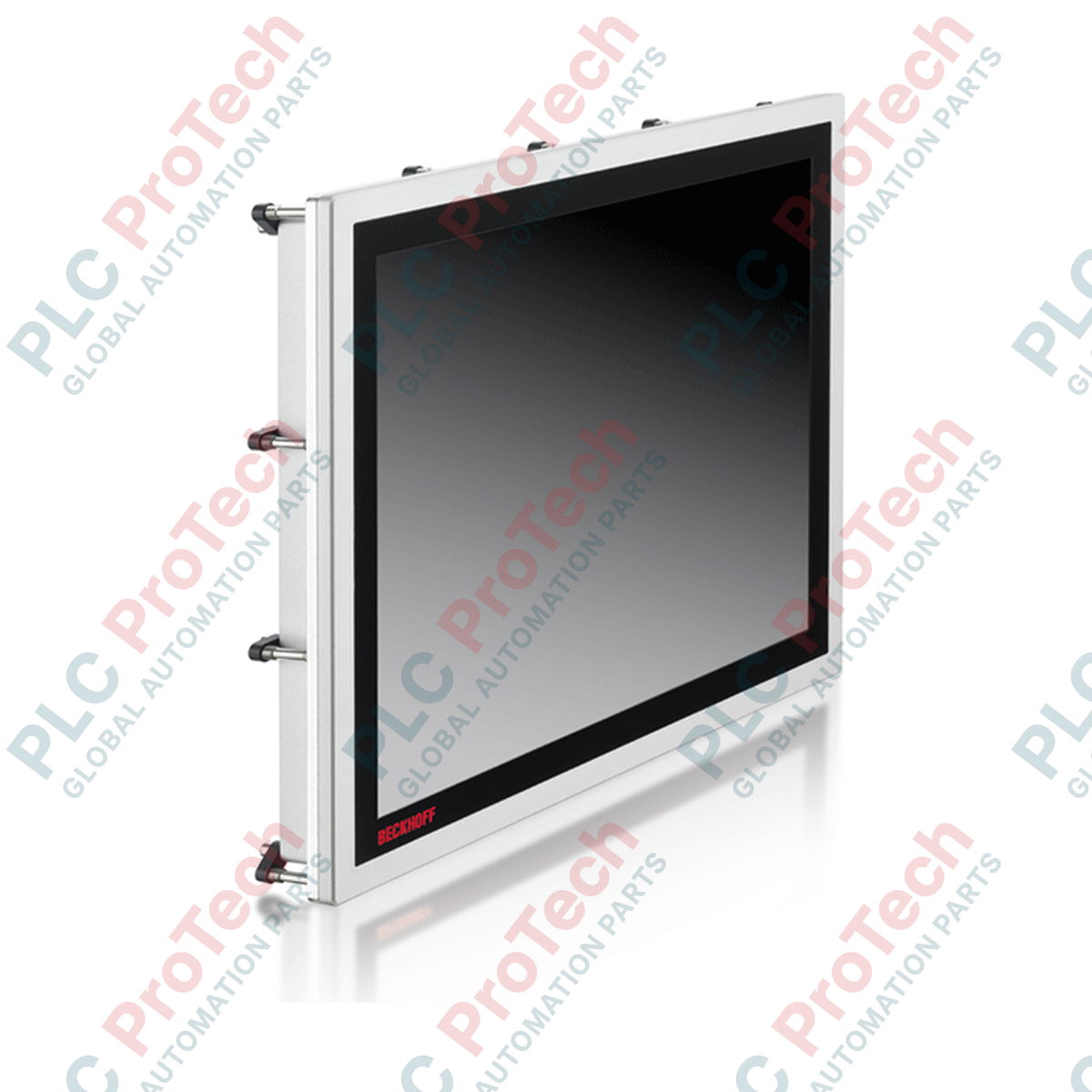
Designed specifically for direct integration in hazardous environments, the Beckhoff CPX2715-0010 provides robust human-machine interface (HMI) performance within Zone 2 and Zone 22 classified areas. Utilizing a fanless cooling topology and a highly durable aluminum housing with an impact-resistant glass front, this built-in Panel PC combines physical resilience with high-performance computing capabilities. The integrated multi-touch capacitive screen supports precise multi-finger operation, making it suitable for modern industrial SCADA, visualization, and PLC control applications.
Features
- Robust aluminum housing with a high-durability glass front, optimized for hazardous Zone 2 and 22 classifications.
- Vibration-resistant pull-out clamping levers for rapid mounting without loose installation accessories.
- Fanless thermal design utilizing heat-dissipating rear cooling fins to eliminate internal dust circulation.
- Highly responsive capacitive multi-touch interface with high-resolution 15-inch visual display.
- Dual high-speed on-board Ethernet interfaces plus expansion options for modular network architecture.
Applications
- Hazardous explosive gas atmospheres classified under ATEX Zone 2 / IECEx Zone 2.
- Combustible particulate environments classified under ATEX Zone 22 / IECEx Zone 22.
- Oil and gas refining, chemical manufacturing, and batching plant operator terminals.
- Pharmaceutical processing plants requiring high-ingress front seals and chemical resistance.
Technical Specifications
| Parameter |
Specification |
| Manufacturer |
Beckhoff |
| Model Number |
CPX2715-0010 |
| Display Size |
15-inch |
| Display Resolution |
1024 x 768 pixels |
| Processor Platform |
Intel Atom E38xx Series (Single-core E3815 1.46 GHz up to Quad-core E3845 1.91 GHz) |
| Memory Options |
2 GB to 8 GB DDR3L RAM |
| Storage Interface |
1 x CFast slot, 1 x 2.5-inch HDD/SSD slot (up to 320 GB CFast) |
| Ethernet Interface |
2 x 100/1000BASE-T on-board (option for 1 additional port) |
| Peripheral Interfaces |
4 x USB 2.0, 1 x DVI |
| Input Supply Voltage |
24 V DC |
| Ingress Protection Rating |
Front: IP65, Rear: IP20 |
| Operating Temperature Range |
0 to 55 degC |
| ATEX/IECEx Classification |
II 3G Ex ec IIC T4 Gc / II 3D Ex tc IIIC T135 degC Dc |
| cFMus Classification |
Class I, II, III, Div 2, Groups A, B, C, D, F, G / Class I Zone 2 AEx ec IIC T4 Gc |
| Country of Origin |
Germany |
| Shipping Weight |
9.00 kg |
Connections and Interfaces
| Terminal / Interface |
Functional Assignment |
| 24 V DC Power Input |
Power supply connector (+24V, 0V, Functional Earth ground) |
| Ethernet (LAN 1 / LAN 2) |
RJ45 interface for industrial control networks and TwinCAT communication |
| USB 1 - USB 4 |
USB 2.0 host interfaces for local mouse, keyboard, or system recovery tasks |
| DVI Out |
External digital display interface for secondary visualization channels |
Empirical Engineering Insights
Alternative Models & Compatibility
The CPX2715-0010 replaces standard, non-classified panel mounts in explosive risk areas. Note that because of the specialized hazardous area protection front, the cutout dimensions match standard CP2715 dimensions, but the mounting clamp pressure specs are significantly stricter to maintain the required Ex tc rating.
Application Pitfalls & Engineering Notes
Since the chassis is fanless, thermal dissipation is heavily dependent on free air convection across the rear cooling fins. Standard installations must preserve at least 50mm of clearance space above and below the rear panel. Operating continuously in unventilated enclosures above 45 degC ambient without checking thermal accumulation can lead to CPU throttling and performance level degradation under TwinCAT 3 runtimes.
Commissioning & Wiring Tips
To prevent electrostatic discharge hazards in hazardous dust environments (Zone 22), the ground connection terminal on the 24V supply connector must be bonded directly to the low-impedance machine reference ground using at least a 4mm squared earthing conductor. Do not use standard painted metallic panels as the sole source of structural grounding.
Installation Guidelines
CRITICAL WARNING:
Ensure all electrical power is disconnected before installing, modifying, or cleaning the Panel PC. In hazardous locations, confirm that the local atmosphere is thoroughly purged and declared safe (non-hazardous) before opening the panel or connecting diagnostic equipment.
1
Insert the Panel PC into the pre-cut panel window from the front side, ensuring the sealing gasket is correctly seated.
2
Secure the unit from the rear using the integrated pull-out clamping levers. Tighten the levers evenly to secure a solid seal against the mounting surface.
3
Connect the low-impedance functional grounding line to the dedicated grounding screw on the housing chassis.
4
Verify correct insertion of your CFast flash or secondary 2.5-inch SSD drive, then wire the 24V DC input supply terminal connector.