Description
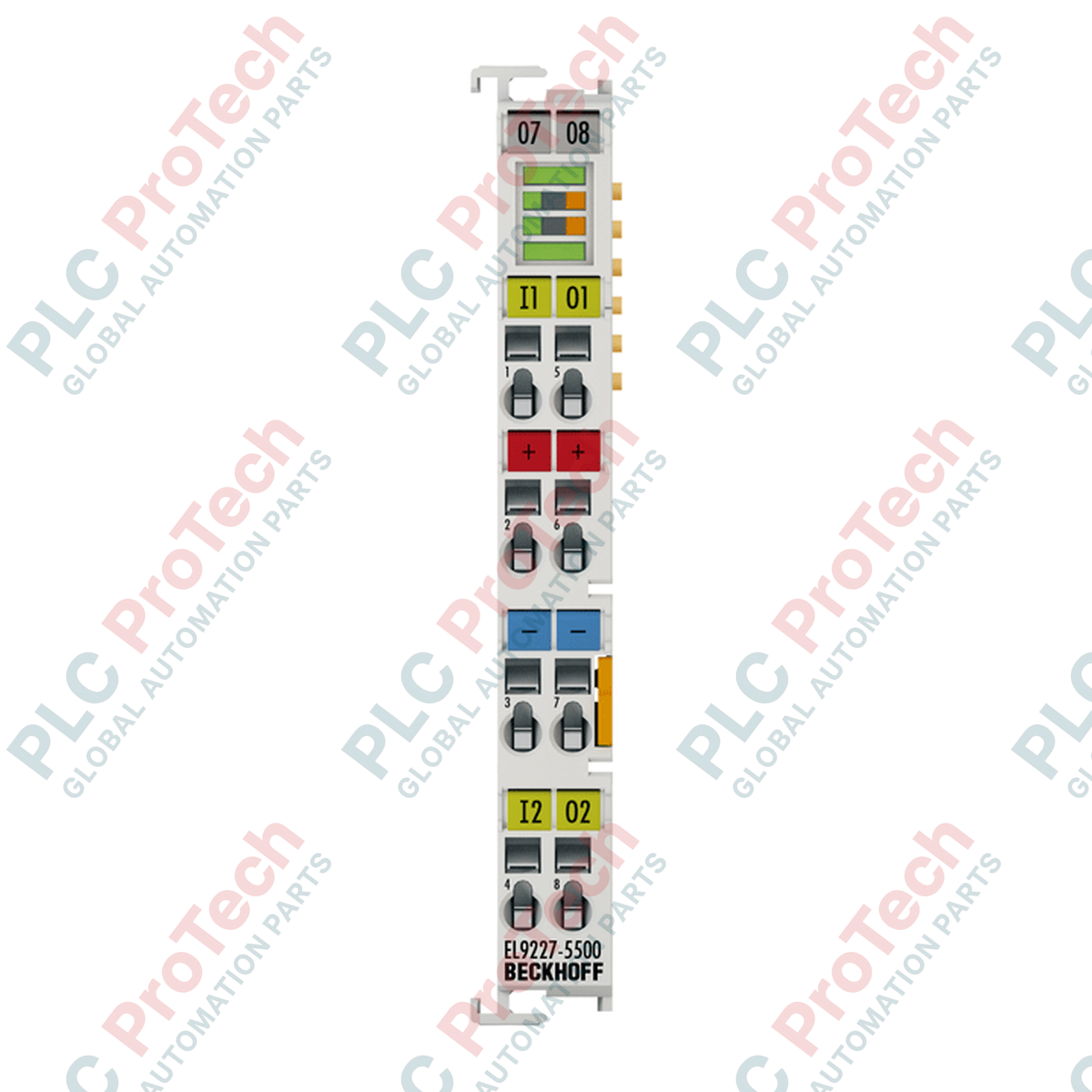
Providing precise circuit-level protection, the Beckhoff EL9227-5500 electronic overcurrent protection terminal distributes and monitors 24 V DC power across two channels within EtherCAT I/O networks. This module integrates adjustable current limit settings, diagnostic pre-warnings, and physical LED status buttons, making it a critical component for safeguarding sensitive field sensors, actuators, and industrial controllers from localized electrical faults. By isolating individual overloaded channels, the terminal prevents system-wide voltage sags and maximizes total machinery uptime.
Features
-
2-Channel Protection: Two independent 24 V DC channels with continuous monitoring and discrete electronic shutdown.
-
Adjustable Current Ratings: Trip currents can be programmed from 1 A to 10 A in steps of 1 A, with a maximum combined sum current of 10 A.
-
Intelligent Diagnostic Warnings: Configurable load warnings (50% to 100%) and low-voltage warnings (17 V to 24 V DC) prevent unexpected downtime.
-
Hardware Redundancy: Dual integrated 15 A fail-safe fast fuses provide hardware-level backup protection on both channels.
-
Enhanced Physical Interfaces: Features integrated LED diagnostic buttons on the front plate for direct manual control and quick local troubleshooting.
Applications
-
Control Cabinet Power Distribution: Safe division of 24 V DC main lines into branch circuits for PLC controllers, HMIs, and networking devices.
-
Industrial Sensor/Actuator Protection: Segmented protection of field devices to prevent localized cable damage or shorts from collapsing the main power rail.
-
Automated Assembly & Robotic Cells: Protects motion control auxiliary lines and safety circuits where temporary overloads may occur.
Technical Specifications
| Technical Parameter |
Specification Value |
| Manufacturer |
Beckhoff |
| Model Number |
EL9227-5500 |
| Nominal Operating Voltage |
24 V DC |
| Number of Channels |
2 (Inputs: 2, Outputs: 2) |
| Rated Output Current |
Adjustable 1 A to 10 A (in 1 A steps; max. sum 10 A) |
| E-bus Current Consumption |
Typically 80 mA |
| Electrical Isolation |
500 V (E-bus / signal voltage) |
| Overvoltage Power-off Threshold |
>= 32 V DC |
| Integrated Fail-Safe Element |
15 A (F) per channel |
| Operating Temperature |
0 to +55 degC |
| Storage Temperature |
-25 to +85 degC |
| Housing Material |
Polycarbonate |
| Dimensions (W x H x D) |
12 mm x 100 mm x 68 mm |
| Connection Cross-Section (Solid/Stranded) |
0.08 to 2.5 mm² (AWG 28 to 14) |
| Connection Cross-Section (with Ferrule) |
0.14 to 1.5 mm² (AWG 26 to 16) |
| Stripping Length |
8 to 9 mm |
| Approvals and Markings |
CE, cULus, cURus |
Empirical Engineering Insights
Alternative Models & Compatibility
The EL9227-5500 differs from the basic EL9227 variants by offering extended configuration capabilities directly via the TwinCAT CoE (CoE directory) system. Standard EL9227 terminals typically use physical rotary switches or fixed parameters. In contrast, the EL9227-5500 allows dynamic adjustments of current steps and warning parameters over the EtherCAT backplane, which requires a corresponding up-to-date ESI (XML) device file inside TwinCAT.
Application Pitfalls & Engineering Notes
Keep in mind that the total sum of current through the power contacts must not exceed 10 A continuously. When installing multiple high-load EL9227-5500 terminals side-by-side, calculate the cumulative thermal profile inside the panel. In unventilated control boxes, operating at ambient temperatures near +55 degC can lower the thermal hold duration of the electronic switch-off, causing premature tripping at transient peak currents.
Commissioning & Wiring Tips
Use standard spring-actuated terminations. For stranded wires, utilizing gas-tight crimped ferrules is highly recommended to prevent micro-arcs and transient resistance fluctuations. Ensure that the 24 V DC common negative rail (0 V) is bonded properly to the primary control cabinet ground to allow reliable detection of low-resistance earth faults.
Installation Guidelines
CRITICAL WARNING:
Risk of arc flash and electrical damage. Isolate all 24 V DC field supply currents and disconnect the main AC/DC control transformer prior to terminal insertion or extraction. Never insert or pull terminals under load.
1
Mount the terminal on a standard 35 mm DIN rail conforming to EN 60715, ensuring the locking slide is secure.
2
Slide the terminal adjacent to the existing EtherCAT terminals so that the lateral tongue-and-groove system and gold power contacts engage cleanly.
3
Strip field wiring cables to 8–9 mm. Depress the terminal spring mechanism with a small flathead screwdriver, insert the conductor, and release to lock.
4
Energize the backplane, run TwinCAT System Manager, scan the EtherCAT box topology, and configure the CoE threshold parameters for output channels 1 and 2.