Description
Designed to bridge high-speed Interbus networks with local IP-Link extension modules, the Beckhoff IL2301-B400 fieldbus coupler box delivers robust decentralized control in demanding environments. This compact, IP67-rated module acts as an intelligent node that coordinates signals between the primary Interbus network and up to 120 local expansion modules via the high-speed IP-Link fiber-optic ring. By housing the control electronics within a fully sealed, mechanically resilient enclosure, the Beckhoff IL2301-B400 eliminates the need for protective electrical cabinets, enabling direct machine-mount installations in areas prone to moisture, dust, and physical vibration.
Key Features
-
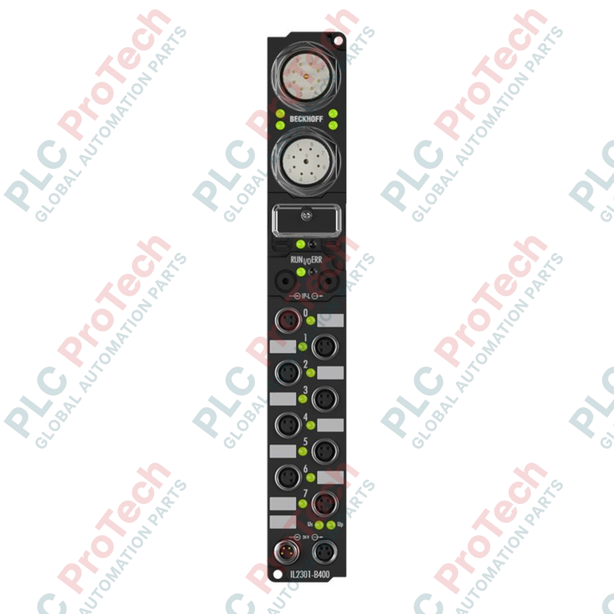
Interbus Integration: Direct connection to copper Interbus-S networks via dual industrial M23 connectors (9-pin male/female).
-
IP-Link Extension Ring: Manages up to 120 extension modules with efficient 64-byte input and 64-byte output data transfers.
-
High Signal Density: Supports up to 512 digital inputs and 512 digital outputs, alongside 28 analog inputs and outputs per station.
-
Rugged Environmental Protection: Certified IP65, IP66, and IP67 ratings for reliable operation in wet, dirty, or washdown conditions.
-
KS2000 Compatibility: Diagnostic and parameter configuration facilitated through the standardized KS2000 serial interface.
Applications
-
Automotive Assembly Lines: Direct mounting on robotic arms and welding fixtures without industrial enclosures.
-
Material Handling & Conveyors: Decentralized sensor/actuator routing along extensive conveyor structures.
-
Packaging Machinery: Wet area washdown zones requiring robust dust and moisture exclusion.
-
Food & Beverage Processing: Distributed I/O setups in high-humidity zones requiring IP67 washdown performance.
Technical Specifications
| Parameter |
Specification |
| Manufacturer |
Beckhoff Automation |
| Model / Article Number |
IL2301-B400 |
| Fieldbus Protocol |
Interbus (Interbus-S) |
| Bus Interface |
1 x M23 female 9-pin, 1 x M23 male 9-pin |
| Control Voltage Supply |
24 V DC (acceptable range 20 to 29 V DC) |
| Box Power Supply Current |
85 mA + sensor consumption (Max. 0.5 A total) |
| Power Supply Connections |
Feed: 1 x M8 male (4-pin); Downstream: 1 x M8 female (4-pin) |
| Isolation Voltage |
Control voltage to fieldbus: None |
| Configuration Interface |
KS2000 serial interface via special connector |
| Operating Temperature |
0 to +55 degC |
| Storage Temperature |
-25 to +85 degC |
| IP Rating |
IP65 / IP66 / IP67 (conforms to EN 60529) |
| Vibration / Shock Resistance |
Conforms to EN 60068-2-6 / EN 60068-2-27 |
| Dimensions (W x H x D) |
30 mm x 126 mm x 26.5 mm (approximate, excluding connectors) |
| Weight |
0.35 kg |
| Shipping Weight (Calculated) |
0.65 kg |
Power Port Connections (M8 Ports)
| Pin Number |
Assignment |
Description |
| Pin 1 |
+24 V DC Control |
Feed for logic operations and internal box control |
| Pin 2 |
+24 V DC Load |
Supply for connected output channels and field devices |
| Pin 3 |
GND Control |
Reference potential for internal control and logic circuit |
| Pin 4 |
GND Load |
Reference potential for output load actuators |
Empirical Engineering Insights
Alternative Models & Compatibility
The B400 variant specifically uses copper Interbus M23 interfaces. Note that Beckhoff also manufactured B408 variants with fiber optic connections. Ensure your existing cabling system matches the copper physics. If substituting older IL2301 units, confirm your local IP-Link fiber lengths; damaged or dirty IP-Link connectors can result in loss-of-link errors that are hard to diagnose over the primary Interbus diagnostics.
Application Pitfalls & Engineering Notes
While the device operates without a protective enclosure, mounting it on high-temperature machinery or in direct sunlight can cause its internal temperature to exceed the +55 degC limit. Provide protective shielding or standoffs when mounting on heat-generating surfaces. Keep track of sensor current draws on the local IP-Link expansion modules; exceeding 0.5 A total on the control power circuit will cause brownouts and communication dropped frames.
Commissioning & Wiring Tips
Always use original Beckhoff IP-Link cables and observe minimum bend radiuses. Sharp bends in plastic optical fibers (POF) result in excessive attenuation, causing sporadic I/O errors. When preparing Interbus M23 connectors, shield continuity must be run fully to the metallic connector shell to minimize high-frequency noise interference from nearby Variable Frequency Drives (VFDs).
Installation Guidelines
CRITICAL SAFETY WARNING
De-energize all power sources (both Control Voltage and Load Voltage) before physically mounting or routing the M23 and M8 connectors. Hot-plugging industrial M8 or M23 connections can cause arcing, damaging sensitive optical interface drivers and corrupting EEPROM parameters.
1
Mount the coupler box directly to the machine chassis using two M4 bolts. Ensure the flat rear face is seated tightly against a clean, paint-free metal surface to maximize thermal dissipation and ground paths.
2
Insert and secure the IP-Link plastic optical fiber (POF) cable links. Ensure clean, perpendicular cuts on the fiber ends to minimize signal loss, and push the connectors in until they lock with an audible click.
3
Connect the incoming and outgoing Interbus M23 connectors, manually tightening the metal knurled rings to maintain IP67 seal integrity. Avoid utilizing power tools to tighten connectors.
4
Plug in the M8 power cables, ensuring independent routing for Control and Load voltages to minimize electromagnetic cross-talk on the sensor lines.