Description
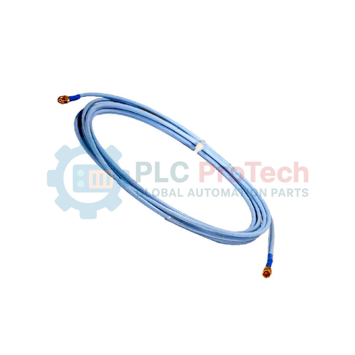
Optimizing the signal transmission path within machinery protection systems, the Bently Nevada 330130-070-02-00 acts as a high-fidelity electrical link between proximity probes and sensor systems. This industrial-grade coaxial extension cable is engineered specifically for integration with the 3300 XL 8mm proximity sensor family, ensuring precise, low-loss transmission of critical eddy current displacement signals over long run distances.
Key Features
-
Precise Electrical Length: Calibrated specifically to 7.0 meters (22.9 feet) to preserve the exact impedance metrics of the complete transducer system.
-
Connector Protection: Features Option 02 integrated connector protectors, safeguarding delicate coaxial junctions from environmental contaminants.
-
Noise Mitigation: Advanced shielding design protects the dynamic signal against electromagnetic interference (EMI) and radio frequency interference (RFI) in high-voltage industrial zones.
-
Robust Mechanical Integrity: High-durability sheath minimizes the risk of physical wear, stretching, or signal degradation.
Applications
- Continuous shaft vibration and axial position tracking on steam and gas turbines.
- Compressor, pump, and electric motor bearings condition monitoring.
- Heavy industrial rotating machinery subject to high thermal and mechanical stress.
Technical Specifications
| Parameter |
Specification Value |
| Manufacturer |
Bently Nevada |
| Part Number |
330130-070-02-00 |
| Compatible Series |
3300 XL 8mm Proximity Transducer System |
| Cable Length |
7.0 meters (22.9 feet) |
| Cable Option |
Standard cable with connector protectors (Option 02) |
| Agency Approval |
Not required (Option 00) |
| Country of Origin |
United States |
| Shipping Weight (Calculated) |
3.0 kg |
Empirical Engineering Insights
Alternative Models & Compatibility
This 7.0-meter extension cable is designed to match standard system lengths (e.g., matching a 1.0-meter probe to achieve an 8.0-meter total system, or a 2.0-meter probe for a 9.0-meter system configuration). Substituting a cable of incorrect length or series will introduce impedance mismatches, distorting the output calibration of the proximitor sensor.
Application Pitfalls & Engineering Notes
Always maintain minimum bend radius requirements during installation. Subjecting the coaxial cable to sharp angles can pinch the dielectric core, causing internal reflections and parasitic signal attenuation that may lead to false vibration readings or unnecessary control system trips.
Commissioning & Wiring Tips
Utilize the integrated connector protectors during field connection to isolate the coaxial interface from aggressive lubricating oils, humidity, and high-frequency electrical noise. Ensure connections are hand-tightened to correct torque specifications using specialized coaxial wrenches to avoid damaging the internal threads.
Installation Guidelines
CRITICAL WARNING: Prior to beginning installation, ensure the respective vibration monitoring rack or proximitor module is de-energized. Do not route coaxial extension cables parallel to high-power motor drive cables or high-voltage lines, as inductive cross-coupling can cause severe signal distortion.
1
Examine both male and female coaxial terminal pins to verify they are free of debris, oxidation, and moisture.
2
Align the connectors carefully and secure the click-lock mechanism. Slide the integrated connector protector fully over the completed connection.
3
Secure the physical cable along the cable tray or conduit, ensuring adequate support and avoidance of potential sharp edges.