Description
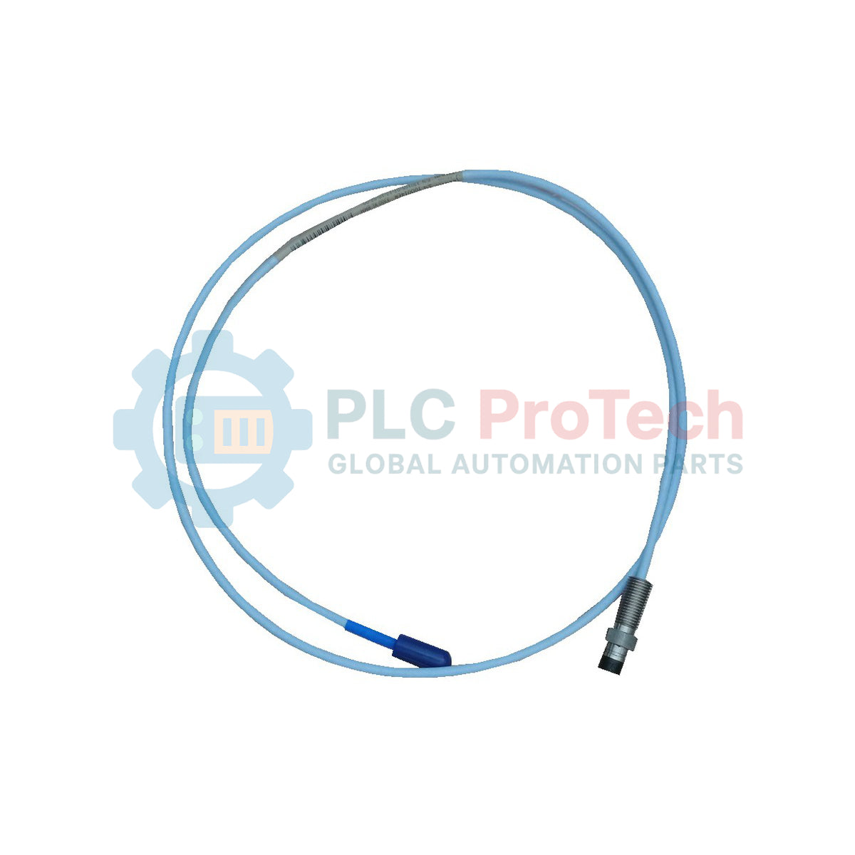
Engineered for high-precision dynamic displacement and vibration measurements within demanding industrial machinery environments, the Bently Nevada 330171-00-32-05-01-CN serves as a critical non-contact transducer element in industrial asset protection systems. This 5 mm proximity probe is optimized for tight mechanical installations where physical clearances restrict the use of standard 8 mm probes, while maintaining the high sensitivity required for fluid-film bearing monitoring. Constructed with a 0.5-meter standard cable and terminating in a miniature coaxial ClickLoc connector with integrated protection, it ensures robust signal integrity and resistance to harsh lubricating oils and moisture.
Key Features
-
Optimized 5 mm Tip Diameter: Ideal for compact spatial arrangements and narrow installation areas.
-
ClickLoc Miniature Coaxial Connector: Features a secure connection mechanism equipped with a connector protector to prevent fluid ingress and mechanical decoupling.
-
Rugged Cable Construction: Fitted with a standard, oil-resistant coaxial cable designed to withstand persistent industrial environments.
-
High-Fidelity Signal Integrity: Delivers precise eddy-current measurement profiles with minimal signal drift over prolonged runtime.
-
Specific Agency Approval: Designated with the "CN" country-specific approval option for direct deployment in restricted regulatory regions.
Applications
- Radial shaft vibration measurements on high-speed turbomachinery.
- Axial thrust position monitoring in centrifugal compressors and pumps.
- Dynamic shaft motion analysis in steam and gas turbine systems.
- Eccentricity measurements on machine tool spindles and auxiliary power units.
Ordering & Configuration Breakdown
| Option Code |
Selected Parameter |
Specification Value |
| 00 |
Unthreaded Length |
0.0 in (0 mm) |
| 32 |
Overall Case Length |
3.2 in (81.3 mm) |
| 05 |
Total Length |
0.5 meter (1.6 feet) |
| 01 |
Connector Option |
Miniature coaxial ClickLoc connector with connector protector, standard cable |
| CN |
Agency Approval |
CN-specific local region approvals |
Technical Specifications
| Manufacturer |
Bently Nevada |
| Part Number |
330171-00-32-05-01-CN |
| Product Series |
3300 5 mm Proximity Transducer System |
| Probe Tip Diameter |
5 mm |
| Connector System |
ClickLoc Coaxial with protective sleeve |
| Cable Type |
Standard coaxial cable (non-armored) |
| Net Weight |
0.323 kg (0.71 lbs) |
| Shipping Weight (Calculated) |
2.0 kg (4.4 lbs) |
| Country of Origin |
United States (USA) |
Connections and Interfaces
| Interface Component |
Connection Profile |
Functional Assignment |
| Center Conductor |
Coaxial Internal Pin |
RF signal transmission and DC bias voltage paths |
| Outer Shield |
Coaxial Outer Collar |
Signal common path and electromagnetic noise shielding |
| ClickLoc Sleeve |
Protector Shell |
Physical shielding against ambient moisture and lube-oil mist |
Empirical Engineering Insights
Alternative Models & Compatibility
This 5 mm probe must be paired exclusively with a matching 5 mm Proximitor Sensor. Mixing a 5 mm probe with a standard 3300 XL 8 mm Proximitor Sensor will alter the nominal system scale factor (typically 7.87 V/mm or 200 mV/mil), leading to severe calibration errors and incorrect machinery protection system action. Verify that the system length calibration (0.5-meter probe + extension cable length) matches the configuration of your Proximitor Sensor (e.g., 5-meter or 9-meter total system length).
Application Pitfalls & Engineering Notes
During mounting in tight bearing housings, ensure that no cross-threading occurs on the 3.2-inch case. Because this unit has an unthreaded length of 0.0 inches, threading begins immediately at the head. A lack of proper thread alignment can damage housing tap threads. Furthermore, maintain the minimum specified bend radius of 25.4 mm (1.0 inch) for the coaxial cable during routing to avoid micro-fracturing the internal signal lines.
Commissioning & Wiring Tips
When joining the miniature coaxial connection to the extension cable, perform a strict electrical isolation check before locking the ClickLoc protector. The resistance between the center conductor and outer shell, with the probe isolated from the target, should read as an open circuit. Verify that the physical connection is completely dry; trace moisture inside the ClickLoc shell introduces a parallel resistance path, mimicking target distance changes and triggering false DC voltage offset faults in the monitor.
Installation Guidelines
CRITICAL WARNING: De-energize all connected instrumentation, monitoring channels, and associated machinery control systems prior to probe installation or physical adjustment. Electrostatic discharge (ESD) or shorting of the coaxial core pin during live operations can cause transient signals that may trigger unexpected safety shutdowns or equipment damage.
1
Mount the probe casing into the threaded bracket or housing port. Rotate by hand to avoid cross-threading, ensuring the unthreaded portion (0.0 inches) remains flush with the target layout interface.
2
Adjust the probe physical gap relative to the target shaft. Use a digital voltmeter connected to the Proximitor Sensor's OUT and COM terminals to monitor the DC gap voltage until the desired operational voltage (nominally -9.0 VDC or as system design directs) is established.
3
Tighten the probe locknut to the recommended mounting torque. Re-verify the gap voltage to confirm the locknut tightening has not shifted the probe's mechanical position.
4
Connect the coaxial cable ClickLoc interface to the corresponding extension cable. Ensure the silicone connector protector is slid firmly over the joint to seal against environmental contaminants.