Description
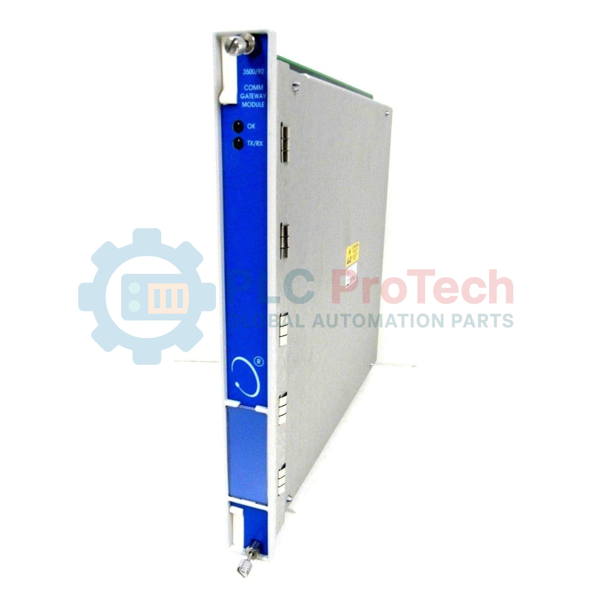
Designed to establish high-speed data translation within machinery protection architectures, the Bently Nevada 3500/92-03-01-CN acts as a dedicated communication gateway module. This module collects and processes status, alarm, and dynamic data from other 3500 monitoring modules in the rack, transmitting this information to external networks via Modbus protocols. The 3500/92-03-01-CN variant is configured with an Ethernet/RS232 Modbus I/O module, low-capacity memory, and holds country-specific agency approvals (CN), making it highly compatible with localized regulatory requirements. It ensures critical machinery diagnostics are immediately accessible to Distributed Control Systems (DCS), Programmable Logic Controllers (PLCs), and SCADA platforms without taxing the main safety backplane bandwidth.
Key Features
-
Dual-Protocol Modbus Interface: Supports simultaneous Modbus RTU serial (RS232/RS422/RS485) and Modbus TCP/IP Ethernet communication.
-
Optimized Latency: Fast internal register mapping minimizes data-refresh delays between the 3500 backplane and the control network.
-
CN Agency Approvals: Fully compliant with specific regional electrical and safety standards for industrial deployments.
-
Ethernet Configurable: Allows easy configuration and troubleshooting using 3500 Rack Configuration software over standard networks.
Industrial Applications
-
Power Generation: Real-time machinery diagnostic transmission for steam and gas turbines.
-
Oil and Gas: Secure integration of offshore compressor monitoring data into centralized SCADA systems.
-
Chemical Processing: Constant machinery health polling for large pump and fan banks in hazardous environments.
Technical Specifications
| Parameter |
Specification |
| Manufacturer |
Bently Nevada (Baker Hughes) |
| Model Code |
3500/92-03-01-CN |
| I/O Module Option |
03 (Ethernet/RS232 Modbus I/O Module) |
| Memory Configuration |
01 (Low Memory Option) |
| Agency Approvals |
CN (China / Country-Specific Approvals) |
| Supported Protocols |
Modbus RTU, Modbus TCP/IP, Proprietary 3500 Protocol |
| Ethernet Port |
RJ45 (10BASE-T / 100BASE-TX) |
| Serial Port |
RS232 (9-pin D-sub or equivalent interface) |
| Country of Origin |
USA |
| Shipping Weight (Calculated) |
2.5 kg (5.5 lbs) |
Connections and Interfaces
| Interface Port |
Function / Circuit Assignment |
| Ethernet RJ45 |
Modbus TCP/IP Host Connection / Static IP Assignment / Configuration Access |
| RS232 (Serial Port) |
Modbus RTU Host Link / Direct Serial Diagnostic Connection |
Empirical Engineering Insights
Alternative Models & Compatibility
The 3500/92-03-01-CN replaces older generation 3500/90 communication modules. It is important to note that the 01 (Low Memory) configuration limits the number of custom-configured Modbus registers. If your architecture demands large-scale custom data map generation containing thousands of contiguous registers, you should check your database design or look into the high-memory (02) version. Always ensure your 3500 Rack Configuration software is updated to match the firmware version installed on this module to prevent communication sync faults during system download.
Application Pitfalls & Engineering Notes
A common issue on-site involves mapping 32-bit floating-point registers. When interfacing this gateway with older PLC units, you may experience byte swapping (Endianness mismatch), which causes incorrect diagnostic values to be displayed. Be prepared to implement word-swapping logic inside the host PLC code. Additionally, avoid running Modbus TCP and serial diagnostics simultaneously on the same logical network loop, as serial translation delays can bottleneck the interface.
Commissioning & Wiring Tips
Ensure that the RS232 serial link is kept below 15 meters (50 feet) to prevent signal degradation in electrically noisy environments. Always use double-shielded twisted pair (S/UTP) cabling for the Ethernet interface and terminate the cable shield directly at the patch panel, rather than letting it float inside the 3500 rack housing.
Installation Guidelines
CRITICAL WARNING: De-energize the entire 3500 instrument rack prior to inserting or extracting the 3500/92 module. Operating under active electrical loads can damage the backplane connector pins. Ground yourself with an approved ESD wrist strap connected to a verified chassis ground point before handling the circuit boards.
1
Verify the chassis slot assignment. The 3500/92 module must reside in any slot other than the Power Supply and Rack Interface Module (RIM) slots. Standard locations are typically located at the leftmost side of the main card cage.
2
Align the main card with the plastic guides in the front of the rack. Gently slide the card backward until it meets the backplane connector, then push firmly until the ejector tabs lock in place.
3
Install the matching I/O module (03 option) into the rear of the rack directly opposite the front main card. Tighten the rear panel screws securely to ensure continuous shielding contact.
4
Apply power, connect your programming PC, and use the 3500 Rack Configuration utility to define the gateway IP address and Modbus register maps.