Gambaran Produk
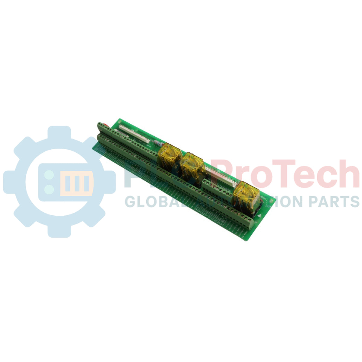
531X171TMAAFG2 adalah Kad Relay Papan Terminal berkeandalan tinggi khusus yang direka oleh General Electric untuk ekosistem pengeksitasi dan pemacu digital EX2000 . Berfungsi sebagai pautan pusat penting untuk penghalaan I/O isyarat dan pemprosesan antara muka kompleks, papan industri ini disambungkan terus ke kad logik pemacu teras melalui kabel reben pelbagai konduktor khusus. Sektor industri berkeperluan tinggi—termasuk kemudahan perlombongan lombong dalam, loji penjanaan kuasa terma, dan infrastruktur pemampatan gas—bergantung pada modul ini untuk memisahkan dengan selamat gelung kawalan digital daripada arus penggerak sisi lapangan. Dengan mewujudkan sambungan maklum balas potensi percuma yang bersih, kad ini membolehkan pengenalpastian anomali awal, melindungi sistem pengkomputeran kawalan hulu daripada lonjakan induktif, menjamin isyarat peranti lapangan yang pantas, dan mengurangkan masa henti loji yang mahal.
Topografi Litar & Protokol Antara Muka
Konfigurasi perkakasan dalaman 531X171TMAAFG2 papan pengawal menumpukan pada pengelompokan terminal yang boleh dipercayai, pengasingan isyarat, dan penggantian modul merentas generasi.
-
Kenalan Kontak Potensi Percuma: Dilengkapi dengan empat laluan relay pertukaran kering berintegriti tinggi yang direka untuk memetakan kemas kini peralatan penting seperti amaran kegagalan kuasa, amaran sistem umum, parameter bateri rendah, dan gelung status bypass aktif.
-
Antara Muka Integrasi Siri Berganda: Mengandungi penyambung USB bersepadu bersama port penyambung Sub-D 9 kutub berat, memudahkan komunikasi pemprosesan lanjutan antara sistem pengkomputeran tempatan dan rangka kerja kuasa sandaran.
-
Penggantian Drop-In: Direka dengan pemetaan jejak yang serasi ke belakang, membolehkan revisi perkakasan khusus ini menggantikan pelbagai papan antara muka GE lama atau rosak tanpa menjejaskan parameter fungsi teras sistem.
-
Rangkaian Pengaktifan Kuasa Rendah: Memerlukan arus operasi hanya 8 hingga 18 V, dengan ambang maksimum 2 W apabila semua relay sentuhan kering didorong serentak ke konfigurasi tertutup.
Data Prestasi & Indeks Sistem
| Parameter Sistem |
Spesifikasi Kejuruteraan |
| Penamaan Model |
531X171TMAAFG2 |
| Pengilang Jenama |
General Electric (GE) |
| Barisan Siri Kawalan |
Platform Pengeksitasi / Pemacu EX2000 |
| Kelas Pengenalan Modul |
Kad Relay Papan Terminal / Antara Muka I/O |
| Input Kuasa Operasi |
Julat Kuasa Operasi 8 hingga 18 VDC |
| Penggunaan Kuasa Modul Maksimum |
2 W maksimum (dengan semua saluran relay ditutup) |
| Tahap Pengaktifan Input Isyarat |
2.4 VDC pada ambang keadaan aktif minimum 1.35 mA |
| Susun Atur Jenis Output |
Kenalan Relay Elektromekanikal melalui Blok Terminal Skru |
| Penarafan Voltan Sentuhan Maksimum |
Had Voltan Sentuhan Maksimum 60 VDC atau 42 VAC RMS |
| Arus Berterusan Maksimum |
1.25 A maksimum (had beban induktif maksimum 50 VA) |
| Had Suhu Sekeliling |
Julat Operasi -10 hingga +40 darjah C |
| Had Suhu Penyimpanan |
-40 hingga +60 darjah C Had Termal Maksimum |
| Negara Pembuatan |
Amerika Syarikat (USA) |
Soalan Lazim Operasi Fungsi & Penyesuaian
Bolehkah 531X171TMAAFG2 menggantikan papan terminal generasi lama secara langsung tanpa perubahan pada pendawaian lapangan?
Tidak, penggantian terus memerlukan kemas kini kecil pada baris lapangan seperti yang diterangkan dalam manual teknikal GE. Contohnya, jika kad rosak sedia ada memetakan wayar ke terminal 24 pada nod ACOM, wayar lapangan itu mesti dipindahkan ke terminal AN1 pada pemasangan papan baru. Selain itu, beberapa laluan terminal memerlukan pemindahan wayar dari kumpulan blok terminal 4TB ke kumpulan blok 3TB pada susun atur baru.
Apakah prosedur yang betul jika input isyarat jatuh di bawah 2.4 VDC semasa ujian sistem?
Voltan input di bawah 2.4 VDC atau arus input kurang daripada 1.35 mA tidak akan mencetuskan optokopler atau gegelung relay di papan dengan boleh dipercayai. Juruteknik mesti mengesan gelung sumber isyarat untuk membersihkan sambungan terminal berketahanan tinggi atau membetulkan penurunan voltan baris pada larian kabel lapangan yang panjang.
Apakah pemboleh ubah kritikal yang menentukan penarafan kuasa maksimum yang dikendalikan oleh output relay?
Sentuhan relay penukar terintegrasi hanya sesuai untuk isyarat voltan rendah sehingga had maksimum 60 VDC atau 42 VAC RMS. Had arus berterusan mutlak ialah 1.25 A, dengan syarat jumlah kuasa reaktif keseluruhan tidak melebihi had 50 VA. Melebihi nilai ini boleh menyebabkan titik sentuhan atau litar jejak melekat serta-merta.
Panduan Kejuruteraan & Pemasangan
-
Pembumian Elektrostatik dan Perlindungan Komponen:
531X171TMAAFG2 mengandungi komponen keadaan pepejal yang sensitif terhadap elektrik statik. Simpan modul dalam beg pelindung anti-statik sehingga saat pemasangan. Kakitangan lapangan mesti memakai tali pergelangan tangan statik yang diikat ke bahagian tidak dicat pada rangka penutup sebelum mengendalikan papan, dan memegang PCB hanya pada tepi fiberglass luarnya untuk mengelakkan minyak kulit dan cas statik daripada menyentuh komponen atau sambungan solder yang terdedah.
-
Peraturan Penyesuaian Terminal dan Pemindahan Wayar:
Apabila menggantikan varian papan lama dengan revisi moden 531X171TMAAFG2, sahkan penetapan terminal mengikut cetakan asal. Apabila menyesuaikan baris dari terminal lama 24, alihkan wayar dari terminal ACOM ke posisi AN1. Pindahkan dengan teliti kumpulan wayar yang dipasang pada pengepala 4TB lama terus ke pemasangan blok terminal 3TB untuk mengekalkan rujukan silang isyarat logik yang betul.
-
Had Tork Terminal dan Kawalan Penyisipan:
Tanggalkan semua baris medan sebanyak 7 mm dan pasangkan ke dalam blok skru tugas berat. Ketatkan semua terminal dengan tork maksimum 0.4 N-m (3.5 inch-lbs) menggunakan pemutar skru industri berinsulasi. Tork berlebihan boleh memecahkan pautan jejak dalaman antara blok terminal dan lapisan papan, manakala tork yang kurang menyebabkan litar terbuka di bawah getaran berat pada dek mesin industri.