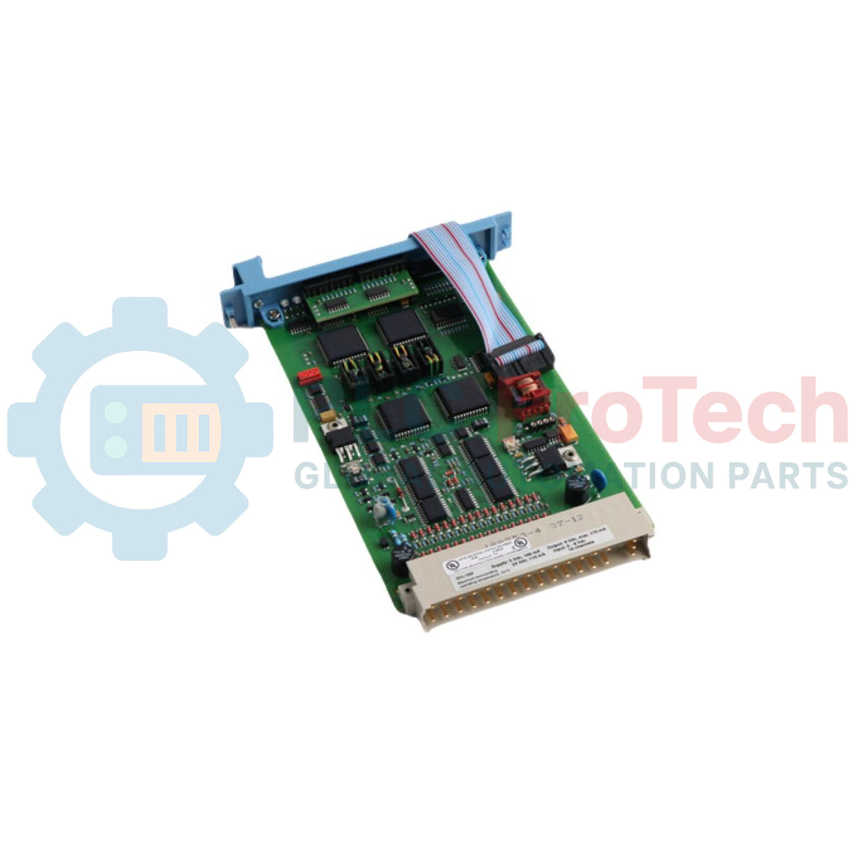
Description
Executing safety-critical loop monitoring within the Safety Manager control architecture, the Honeywell FC-SDIL-1608 functions as a highly reliable safety digital input module specifically configured for active line monitoring. This module integrates seamlessly into SIL-rated safety instrumented systems (SIS) to process field inputs from proximity sensors and mechanical switches while continuously diagnosing field wiring integrity. By incorporating dedicated DIN 19234 (NAMUR) compliant interfaces, the device ensures prompt detection of open-circuit and short-circuit faults across its 16 input channels.
Features
-
16 Fully Isolated Input Channels: Supports up to 16 independent safety digital inputs per module.
-
NAMUR Compliance: Interfaces directly with field devices conforming to the DIN 19234 standard.
-
Integral Line Monitoring: Active detection of open-loop and short-circuit line faults via precise current threshold windowing.
-
Short-Circuit Proof Loop Supply: Embedded 8 VDC loop supply limited to 170 mA to prevent field wiring faults from affecting internal backplane electronics.
-
Compact Form Factor: Standard 4 HP (TE) width and 3U (HE) height matching Safety Manager subrack slots.
Applications
- Emergency Shutdown Systems (ESD)
- Fire and Gas (F&G) safety loops
- Burner Management Systems (BMS)
- NAMUR proximity sensor monitoring in hazardous areas
Technical Specifications
| Parameter |
Specification Value |
| Manufacturer |
Honeywell |
| Model / Part Number |
FC-SDIL-1608 |
| Input Channels |
16 Channels |
| Input Type |
DIN 19234 (NAMUR) compliant |
| Switching Levels |
1.4 mA to 1.9 mA |
| Hysteresis |
0.2 mA ± 0.05 mA |
| Input Filter |
First-order, low-pass 100 Hz |
| Field Wire Resistance |
Maximum 50 Ohms |
| 8 V Loop Supply Voltage |
7.9 V to 8.7 V |
| 8 V Loop Supply Current |
170 mA (Short-circuit proof) |
| 5 Vdc Current Draw |
160 mA |
| 24 Vdc Current Draw |
110 mA |
| Physical Dimensions |
4 TE width, 3 HE height (4 HP, 3U) |
| Approvals |
CE, TUV, UL, CSA, FM |
| Shipping Weight |
2.0 kg |
Empirical Engineering Insights
Alternative Models & Compatibility
The FC-SDIL-1608 is highly compatible with standard Honeywell Safety Manager backplanes. When migrating from legacy or non-line monitored safe input cards, note that the 1608 variant enforces tight window diagnostics. Switching logic transitions depend strictly on current thresholds (1.4 mA to 1.9 mA) following DIN 19234 standards. Replacing standard dry contact digital input modules with this card requires installing parallel and series line resistors at the switch contact to enable proper diagnostic currents.
Application Pitfalls & Engineering Notes
A common issue during deployment is line fault trips caused by excessive field loop resistance. If the field wire resistance exceeds the 50 Ohm specification limit, voltage drops can push the active state current below the 1.4 mA threshold, generating false open-circuit diagnostic warnings in the Safety Manager system logs. Additionally, ensure the total current draw across all 16 channels does not exceed the power supply limits, especially in environments with high ambient noise or long field runs.
Commissioning & Wiring Tips
For maximum noise immunity in hazardous or high-EMI environments, run field lines using shielded twisted-pair cables. Ground the shield exclusively at the marshaling cabinet's safety earth bar; never ground the shield at both ends to avoid hazardous ground loops. During initial commissioning, use a calibrated digital multimeter to verify that the active loop current lies comfortably in the range of 1.2 mA to 2.1 mA under stable operating conditions to prevent nuisance trips during thermal cycling.
Installation Guidelines
CRITICAL WARNING
Disconnect all primary and secondary power sources prior to inserting or removing the safety module from the subrack. Failure to fully de-energize the unit can damage sensitive backplane connections, compromise the SIL safety rating of the rack, and create transient faults across adjacent safety-critical modules.
1
Subrack Alignment:
Align the module card edge carefully with the designated guide rails of the 3U subrack slot, ensuring correct polarization key matches.
2
Secure Backplane Mating:
Gently slide the module inward until the backplane connectors seat firmly. Secure the card in place by tightening the front panel retaining screws to the specified torque.
3
Field Wiring Verification:
Confirm that NAMUR loop terminal connections match the configured pin configurations before executing power-up diagnostic routines via the Safety Builder software.