Description
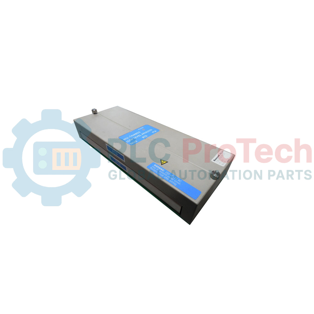
Designed for seamless integration within legacy TDC 3000 and Experion safety or control architectures, this Honeywell MU-TAMR03 serves as a specialized Low Level Analog Multiplexer (LLMux) Field Termination Assembly (FTA) dedicated to RTD temperature sensor interfaces. Operating as a critical link between field-level RTDs and the Low Level Analog Input Multiplexer (LLMux) Input/Output Processor (IOP), this module enables high-density, millivolt-level temperature data acquisition. The assembly features robust compression terminals for point-to-point field wiring and is specifically engineered for non-redundant configurations in controlled control room environments.
Features
-
High-Density Interface: Supports up to 16 independent low-level analog input channels for RTD measurement.
-
Compression Terminal Blocks: Features secure, direct compression connections to accommodate standard field wiring without soldering or specialized lugs.
-
Single IOP Architecture: Configured for non-redundant, single-channel interface systems, maximizing slot efficiency in standard loops.
-
TDC 3000 Compatibility: Engineered to connect via standard Honeywell proprietary cabling directly to the LLMux IOP card.
Applications
-
Power Generation: High-density temperature monitoring of bearing housing, stator windings, and exhaust gases.
-
Refining and Petrochemicals: Multi-point RTD tracking on distillation columns and heat exchangers.
-
Pulp and Paper: Multi-channel continuous thermal profiling in harsh drying sections.
Ordering Information
| Model Number |
Part Number |
Terminal Type |
Conformal Coating |
| MU-TAMR03 |
51309218-125 |
Compression |
No (Uncoated) |
| MC-TAMR03 |
51309218-175 |
Compression |
Yes (Conformally Coated) |
| MU-TAMR13 |
51309218-225 |
Screw Terminal |
No (Uncoated) |
Technical Specifications
| Manufacturer |
Honeywell |
| Model Reference |
MU-TAMR03 |
| Part Number |
51309218-125 |
| Module Type |
Low Level Analog Input Multiplexer RTD FTA |
| Number of Channels |
16 Channels |
| Terminal Type |
Compression Terminals |
| Redundancy Support |
Not Supported (Single IOP Only) |
| Conformal Coating |
No |
| CE Compliance |
No |
| Operating Temperature |
0 to 60 degC |
| Country of Origin |
USA |
| Shipping Weight (Calculated) |
2.5 kg / 5.5 lbs |
| Package Dimensions (Calculated) |
31.0 x 14.5 x 8.0 cm (12.2 x 5.7 x 3.1 in) |
Connections and Interfaces
The MU-TAMR03 routes 3-wire RTD connections from the field directly to the LLMux multiplexing circuitry. Each of the 16 channels requires three dedicated termination points to ensure accurate lead-wire resistance compensation.
| Terminal Node Name |
Signal Assignment |
Description |
| A |
RTD Source (+) |
Current excitation source line to the RTD sensor element. |
| B |
RTD Sense (-) |
Voltage sensing return path for lead-wire resistance calculation. |
| C |
RTD Return / Shield |
Common reference return and instrumentation shield grounding point. |
Empirical Engineering Insights
Alternative Models & Compatibility
The 51309218-125 (MU-TAMR03) belongs to the non-conformally coated class of TDC 3000 assemblies. For harsh or corrosive petrochemical installations, engineers must specify the MC-TAMR03 (51309218-175), which incorporates a protective conformal coating layer. Additionally, if your facility standardizes on screw-type termination barriers rather than compression clamps, the MU-TAMR13 variant should be deployed instead.
Application Pitfalls & Engineering Notes
Because this FTA is a non-redundant system, the loss of this module or its direct serial cable interface will cause the immediate drop of all 16 analog monitoring loops. Crucially, as an uncoated board, placing the MU-TAMR03 in an environment subject to condensing humidity or corrosive gases (such as hydrogen sulfide) will lead to early degradation of the analog multiplexing chips, resulting in erratic, drifting, or open-circuit RTD error statuses.
Commissioning & Wiring Tips
To maintain maximum accuracy, ensure all three wires of the RTD circuit have the identical physical resistance. Discrepancies in wire length or contact oxidation at the compression terminals will degrade the lead resistance compensation calculation inside the LLMux IOP. During commissioning, run high-quality shielded twisted-pair cables, and ensure the shield drain wire is terminated only at the designated FTA shield ground terminal to mitigate ground loop noise.
Installation Guidelines
CRITICAL WARNING
Before installing or servicing the FTA, verify that all system power sources associated with the IOP rack and field instrumentation are fully de-energized. Failure to isolate power paths can lead to short circuits, permanent damage to the multi-channel multiplexing circuitry, or false control loops in active processes.
1
Mount the FTA card securely to the cabinet DIN rail or standard mounting plate inside a dust-free, environmentally controlled enclosure.
2
Connect the dedicated LLMux serial interface cable from the FTA card socket to the corresponding channel connector on the non-redundant IOP card.
3
Strip field RTD cables back 6mm and insert individual conductors into the compression block terminals. Hand-tighten the retention screws firmly, ensuring no bare copper wire is exposed.