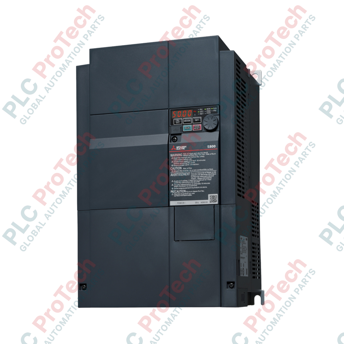
Description
Integrating the Mitsubishi Electric FR-E840-0380-4-60 within an industrial motor control network delivers precise speed regulation and reliable torque management for demanding three-phase systems. This 400V class variable frequency drive from the FR-E800 Series features a Normal Duty (ND) rated current of 38A, specifically engineered with safety-stop capabilities and a robust circuit board coating to survive harsh industrial environments.
Features
-
Voltage Class: High-performance 400 V class design optimized for global standard three-phase power supplies.
-
Conformal Coating: Circuit boards feature a protective coating (-60 specification) to defend against dust, humidity, and corrosive gases.
-
Flexible Control Logic: Configured for source logic control input and a source-logic fixed safety stop signal.
-
Monitoring and Output: Built-in AM terminal provides precise voltage-based analog monitoring.
-
Advanced Thermal Design: Designed without plated conductors, prioritizing material durability and consistent heat dissipation.
Applications
- Conveyor and material handling systems requiring strict torque control.
- Industrial fans, exhaust blowers, and centrifugal pumping systems.
- Packaging, wrapping, and labeling machinery.
- Textile, paper processing, and manufacturing machinery.
Technical Specifications
| Parameter |
Value |
| Manufacturer |
Mitsubishi Electric |
| Model Number |
FR-E840-0380-4-60 |
| Series |
FR-E800 |
| Input Voltage Class |
400 V Class (Three-Phase Input) |
| Normal Duty (ND) Rated Current |
38.0 A |
| Rated Frequency |
50 Hz (Initial setting) |
| Input Signal Logic |
Source logic (Initial status) |
| Safety Stop Signal |
Source logic (Fixed) |
| Monitoring Protocol Spec |
Voltage (Terminal AM) |
| Circuit Board Protection |
With coating (-60 spec) |
| Plated Conductor |
Without plated conductors |
| Net Weight |
11.0 kg |
| Shipping Weight (Calculated) |
14.0 kg |
Connections and Interfaces
| Terminal / Port |
Function / Circuit Assignment |
| AM |
Analog voltage output monitoring terminal. |
| S1, S2, SC |
Safety stop input circuit terminals (Source logic configuration). |
| R/L1, S/L2, T/L3 |
Three-phase AC power input terminals. |
| U, V, W |
Three-phase AC output connections to the motor. |
Alternative Models & Compatibility
The FR-E840-0380-4-60 belongs to the modern FR-E800 generation, succeeding many legacy FR-E700 series models. When migrating, note that the physical dimensions and terminal positions may vary. Suffixes like "-60" are critical for installations in aggressive, high-humidity, or chemical-heavy production plants; using standard non-coated variants in these settings will drastically reduce the Mean Time Between Failures (MTBF).
Application Pitfalls & Engineering Notes
When designing sealed control enclosures, do not rely purely on the integrated cooling fan. A 38A drive dissipates significant thermal energy under high-load cycles. Ensure local cabinet venting is calculated to prevent internal temperatures from exceeding 50 degC. Ensure that the source logic safety inputs are configured only with safe, isolated external power supplies to prevent common-mode noise issues.
Commissioning & Wiring Tips
Always run motor power cables and control/signal lines in separate, isolated metal conduits. Keep the distance between the drive output terminals (U, V, W) and the motor as short as possible; if motor cables exceed 30 meters, installing an output AC reactor is highly recommended to suppress parasitic capacitive currents and protect the motor insulation from high dV/dt voltage spikes.
Installation Guidelines
CRITICAL WARNING: Hazardous voltages remain present in the internal DC bus capacitors even after the mains power supply is isolated. Disconnect all primary power and wait at least 10 minutes. Confirm that the charge lamp is fully extinguished and verify the voltage across the main circuit terminals is near 0 V before attempting to wire or inspect the unit.
1
Mount the inverter vertically on a flat, non-flammable surface. Ensure clear air-flow zones of at least 50 mm above and below the drive framework.
2
Connect the physical earth ground wire directly to the drive's dedicated grounding terminal before wiring power input paths.
3
Terminate the three-phase AC power supply wires to R/L1, S/L2, and T/L3. Connect the output lines U, V, and W to the motor terminals.
4
Double-check safety stop wiring jumpers and logic selection settings before energizing the device for initial test rotation.