Description
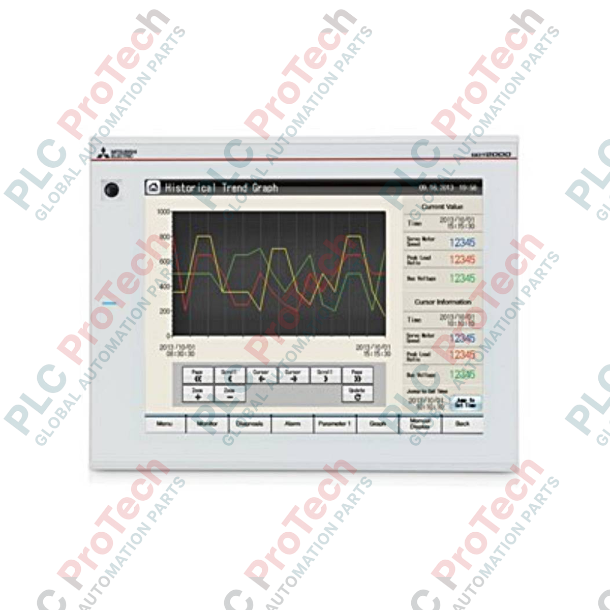
Engineered to deliver high-performance human-machine interface functionality in demanding industrial environments, the Mitsubishi Electric GT2710-VTWA acts as an advanced control panel node within the GOT2000 Series platform. This high-specification graphic operation terminal is equipped with intuitive multi-touch gesture functions, enabling operators to swipe, pinch, and zoom for precise visualization and machine control. Featuring a 10.4-inch TFT color display, a clean white frame bezel, and wide-range AC power compatibility, this terminal ensures optimal system monitoring, alarm diagnostics, and data logging capabilities direct from the control enclosure.
Key Features
-
Multi-Touch Gesture Control: Supports intuitive multi-finger operations to prevent accidental triggers and improve operational efficiency.
-
VGA TFT Display: Crisp 640 x 480 resolution display with a high-contrast backlight for visual clarity in poorly lit control rooms.
-
Flexible Installation Layouts: Engineered to support both horizontal and vertical mounting alignments with automatic temperature de-rating.
-
Robust Environmental Tolerance: Designed to meet stringent industrial standards for vibration, shock, and noise immunity.
-
Broad Communication Port Folio: Integrated Ethernet, RS-232, RS-422/485, USB host/device, and SD card interfaces for streamlined system connectivity.
Applications
-
Automotive Assembly Plants: Serving as the primary interface for body-in-white and conveyor control architectures.
-
Food & Beverage Processing: Cleanroom and washdown environments requiring high-visibility monitors with clean white frame profiles.
-
Packaging and Material Handling: Real-time monitoring of complex multi-axis motion and high-speed sorting systems.
-
Water and Wastewater Treatment: Decentralized monitoring stations utilizing robust Ethernet-based fieldbus topologies.
Technical Specifications
| Parameter |
Specification Value |
| Manufacturer |
Mitsubishi Electric |
| Model Number |
GT2710-VTWA |
| Series |
GOT2000 Series (GT27) |
| Display Type |
TFT Color LCD |
| Screen Size |
10.4 inches |
| Resolution |
640 x 480 Pixels (VGA) |
| Frame Color |
White |
| Input Power Supply Voltage |
100 to 240 VAC (+10%, -15%) |
| Power Consumption (Max) |
41 W or less |
| Inrush Current |
60 A or less (2 ms, ambient 25 degC, max load) |
| Operating Ambient Temperature |
0 to 55 degC (horizontal), 0 to 50 degC (vertical) |
| Operating Ambient Humidity |
10 to 90% RH (non-condensing) |
| Insulation Resistance |
10 MOhm or higher (500 VDC) |
| Applicable Wire Size |
0.75 to 2 mm² |
| Terminal Block Screw |
M3 (Tightening torque: 0.5 to 0.8 N.m) |
| External Dimensions (W x H x D) |
303 mm x 218 mm x 52 mm |
| Net Weight (Excl. Brackets) |
2.1 kg |
| Shipping Weight (Calculated) |
8.0 kg |
Connections and Interfaces
| Interface Type |
Connector / Pin Configuration |
Function / Protocol Support |
| Ethernet Port |
1x RJ-45 Channel |
Modbus/TCP, MC Protocol, Host PLC Communications |
| Serial Interface (CH1) |
D-Sub 9-pin Male |
RS-232 serial programming, peripheral connectivity |
| Serial Interface (CH2) |
D-Sub 9-pin Female |
RS-422/485 multi-drop network links |
| USB Ports |
Type-A (Host) / Type Mini-B (Device) |
Data export, firmware transfer, external mouse/keyboard |
| Storage Slot |
1x SD Memory Card Slot |
OS backup, project storage, and CSV logging parameters |
Empirical Engineering Insights
Alternative Models & Compatibility
When migrating legacy systems from the GT16 or GT15 series to the GT2710-VTWA, screen configuration layouts can be upscaled using the GT Works3 software tool. Note that the "W" in the product suffix dictates a specialized white bezel; check chemical compatibility when utilizing this version in food-processing operations where aggressive sanitation agents are in use. For drop-in mechanical sizing, ensure panel cutouts precisely match the standard GOT2000 10.4-inch dimensions.
Application Pitfalls & Engineering Notes
Thermal performance varies based on mounting geometry. When mounted vertically, the internal convective heat flow is restricted; therefore, the maximum safe operating temperature is reduced to 50 degC. Ensure at least 100 mm of clear space is maintained between the rear of the terminal and adjacent circuit components (such as variable frequency drives or high-power contactors) to mitigate induced heat and localized hotspots.
Commissioning & Wiring Tips
To protect the sensitive electronics on the power board, the terminal block must be wired with class-appropriate terminal lugs (RAV1.25-3 or V2-S3.3). Grounding must be completed using a dedicated ground wire with a cross-section of 2 mm² or larger, connected directly to a Class-3 protective ground bus. Avoid routing the terminal's power lines parallel to motor output lines or primary utility feeders to eliminate electromagnetic interference.
Installation Guidelines
CRITICAL WARNING:
Before initiating mounting, physical installation, or wire terminations on the terminal block, isolate all AC mains distribution lines. Confirm with a calibrated digital multimeter that no stray residual charge or live voltage exists at the terminal block. Failure to de-energize can damage internal logic layers and present an immediate risk of electrical shock to commissioning staff.
1
Perform a pre-cutout validation. Verify panel frame thickness is between 2.0 mm and 4.0 mm to guarantee a proper IP67F environmental front seal.
2
Insert the terminal directly into the clean-cut panel window, ensuring the pre-installed dust-gasket does not slip or bind during placement.
3
Tighten all supplied panel mounting brackets in a cross-diagonal sequence to a uniform torque rating of 0.20 to 0.25 N.m. Over-torqueing will distort the front bezel.
4
Attach the M3 ground cable first, and then proceed with the L1 and N power terminations, ensuring the terminal block's screws are locked to 0.5 - 0.8 N.m.