Description
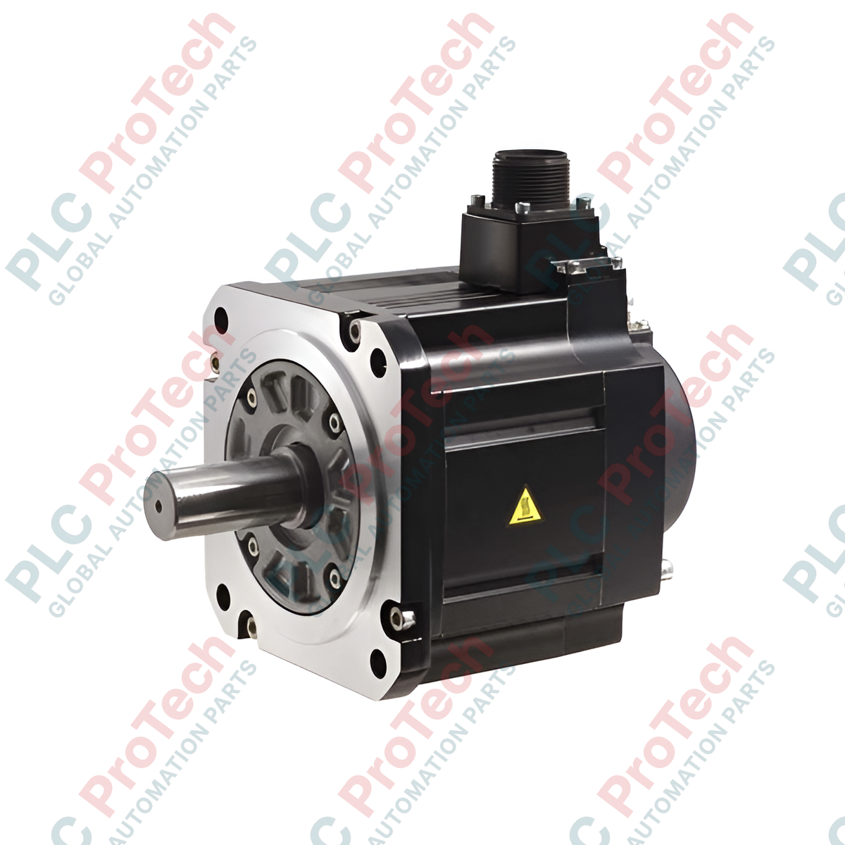
Engineered for high-inertia industrial motion control, the Mitsubishi Electric HG-SR301BJ represents a robust AC servo solution designed to deliver precise torque and speed synchronization within demanding automation architectures. Incorporating a factory-fitted electromagnetic brake and a protective oil seal, this HG-SR Series motor is optimized for positioning applications requiring high torque at lower operational speeds. Its medium-capacity design makes it highly suitable for integration with MR-J4 servo amplifiers, ensuring seamless communication and high-resolution encoder feedback.
Key Features
-
High-Inertia Capability: Ideal for applications with fluctuating loads or heavy-duty mechanical linkages.
-
Electromagnetic Brake: Integrated holding brake configuration for secure position retention during power-off states.
-
Industrial Protection: Outfitted with an integrated oil seal to safeguard internal windings against industrial fluids.
-
Thermally Stable: Designed for continuous duty cycles under standard operating temperatures.
Applications
- Heavy material handling and gantry positioning systems.
- Metal processing and stamping press feed systems.
- Large-scale packaging and indexing machinery.
- Rotary table drives and high-torque machine tool axes.
Technical Specifications
| Manufacturer |
Mitsubishi Electric |
| Model Number |
HG-SR301BJ |
| Series Name |
HG-SR Series |
| Rated Output |
3.0 kW |
| Rated Speed |
1000 r/min |
| Electromagnetic Brake |
Yes (Holding Brake) |
| Oil Seal |
Yes (Integrated) |
| Operating Temperature |
0 to 40 degC (non-freezing) |
| Storage Temperature |
-15 to 70 degC (non-freezing) |
| Ambient Humidity |
Operating: 80% RH or less; Storage: 90% RH or less |
| Installation Environment |
Indoors, free of corrosive/flammable gases, oil mist, and dust |
| Altitude |
Maximum 1000 m above sea level |
| Vibration Resistance |
X-axis: 24.5 m/s2, Y-axis: 29.4 m/s2 |
| Net Weight |
26 kg |
| Shipping Weight (Calculated) |
27 kg |
Empirical Engineering Insights
Alternative Models & Compatibility
This unit is built to interface directly with Mitsubishi MR-J4 servo drive architectures. When substituting older HC-SFS series motors, verify amplifier firmware compatibility, parameter configuration adjustments, and shaft physical envelope clearances. Suffix "BJ" indicates a dedicated electromagnetic brake and an oil seal; standard "G" or non-brake variants are not direct plug-and-play drops without re-engineering the emergency-stop control loops and dynamic braking profiles.
Application Pitfalls & Engineering Notes
While the oil seal prevents lubricant ingress from gearboxes, continuous submersion or excessive splashing can compromise the sealing lip over extended operation. Ensure proper runout checks on the mechanical coupling to avoid radial or axial load concentrations that exceed the mechanical shaft bearing ratings, as excessive loading leads to premature bearing failure and high audible noise levels.
Commissioning & Wiring Tips
Always decouple the motor from the mechanical load during initial direction-of-rotation and encoder phasing checks. Run the motor's 24V DC brake supply on a dedicated, stabilized DC power line separate from the main controller logic power supply to prevent noise coupling and unexpected voltage drops that may cause brake chatter.
Installation Guidelines
CRITICAL WARNING
Ensure all primary input power and auxiliary drive control circuits are completely de-energized and locked out before attempting installation or maintenance. Verify the DC bus voltage on the companion amplifier has fully discharged before handling any terminal connections.
1
Align the servo motor axis precisely with the load shaft using flexible couplings to minimize misalignment stresses.
2
Securely mount the motor flange to a rigid, flat, heat-dissipating surface using correct torque specifications for the mounting bolts.
3
Connect the motor power cable, encoder feedback line, and brake control lines, maintaining clear physical segregation from high-voltage supply lines to suppress electromagnetic interference.
4
Establish solid system ground connections at the designated grounding points on both the motor housing and the drive amplifier chassis.