Description
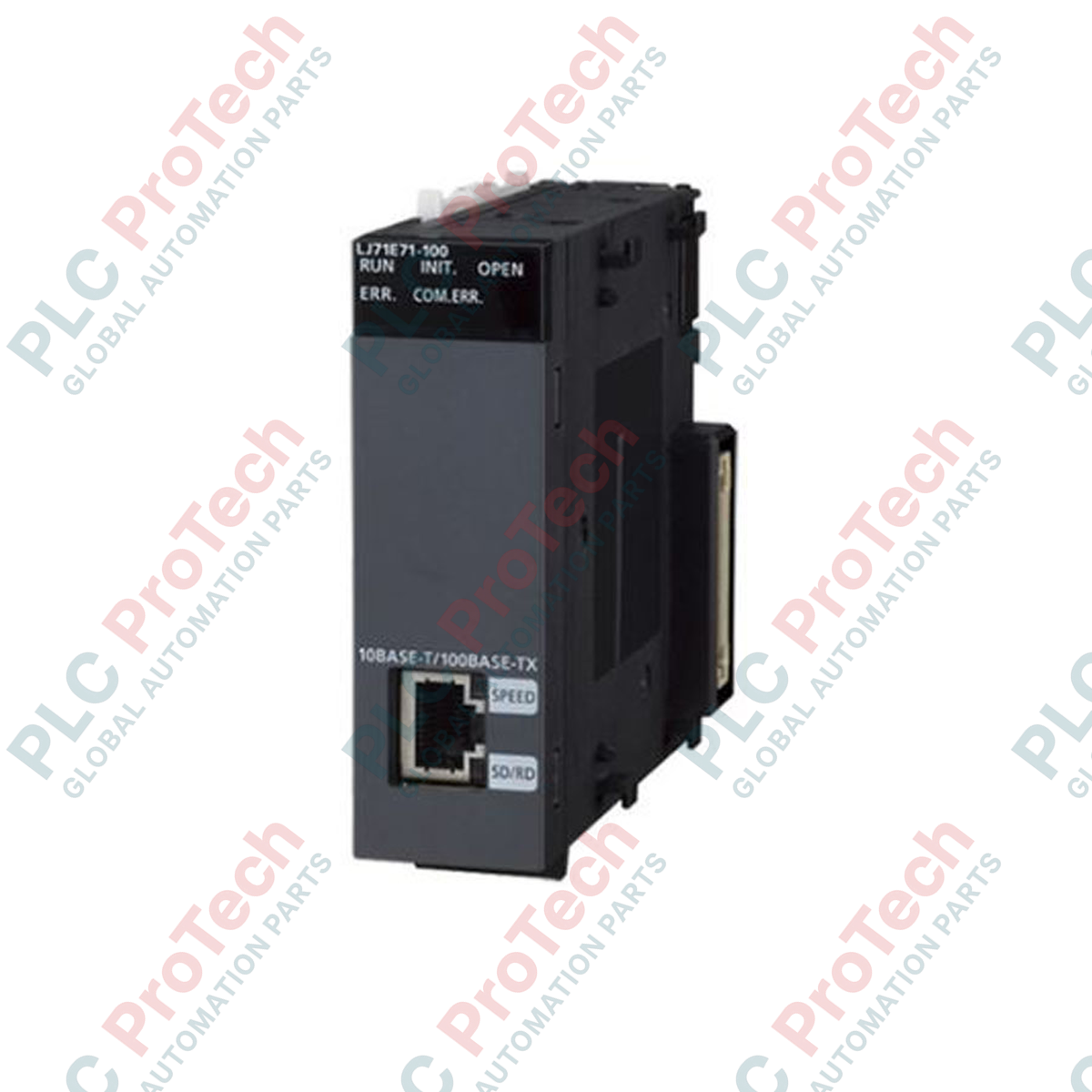
Providing high-speed Ethernet connectivity directly to MELSEC L Series architectures, the Mitsubishi Electric LJ71E71-100-CM manages robust plant-level data transmission and programming tasks. This module enables fast, reliable industrial network communications by acting as a gateway between the processor unit and supervisor-level SCADA systems, HMIs, or other controllers. Featuring dual-rate physical media support for 100BASE-TX and 10BASE-T networks, the module seamlessly processes intensive data payloads while maintaining low internal bus current draw. Built-in system functions allow for easy remote maintenance, diagnostic monitoring, and configuration changes directly through the GX Works2 programming software platform.
Features
-
Multi-Protocol Support: Compatible with MELSOFT connection, SLMP (MC protocol), Socket communication, and pre-defined developer protocols.
-
Flexible Network Access: Built-in Web functions and E-mail transmission utilities allow for direct remote troubleshooting and diagnostics.
-
Auto-Negotiation: Built-in transceiver automatically adjusts between 100 Mbps and 10 Mbps operational speeds depending on the network switch environment.
-
Compact L-Series Form Factor: Integrates directly onto the L-Series DIN-rail mount system without requiring a bulky dedicated base unit.
Applications
- Distributed industrial control networks linking multiple PLC systems across large manufacturing plants.
- Real-time communication and variables transmission between PLC units and HMI/SCADA management interfaces.
- Remote programming, diagnostic monitoring, and automated alarm notification via standard email services.
Technical Specifications
| Manufacturer |
Mitsubishi Electric |
| Model Number |
LJ71E71-100-CM |
| Product Series |
MELSEC L Series |
| Module Type |
Ethernet Interface Module |
| Data Transmission Speed |
100 Mbps (100BASE-TX) / 10 Mbps (10BASE-T) |
| Communication Port Type |
RJ45 female connector |
| Internal Current Consumption (5 VDC) |
0.60 A |
| Max Simultaneous Connections |
16 connections |
| Shipping Weight (Calculated) |
0.45 kg |
| Package Dimensions (Calculated) |
130 mm x 110 mm x 45 mm |
Connections and Interfaces
| Connector Pin |
Function / Assignment |
| Pin 1 |
TX+ (Transmit Data +) |
| Pin 2 |
TX- (Transmit Data -) |
| Pin 3 |
RX+ (Receive Data +) |
| Pin 6 |
RX- (Receive Data -) |
Empirical Engineering Insights
Alternative Models & Compatibility
The LJ71E71-100-CM is physically and functionally drop-in compatible with standard MELSEC L Series CPU systems. The "-CM" suffix indicates regional industrial standard compliance configurations, though identical Ethernet configurations apply inside GX Works2. In legacy migrations, verify your CPU unit firmware supports multi-connection network interfaces before integrating this module to prevent communication timeout faults.
Application Pitfalls & Engineering Notes
When adding the Ethernet module to an active L-Series CPU stack, recalculate your internal 5 VDC system bus current draw. This unit draws a constant 0.60 A. If combined with multiple positioning modules or high-density digital I/O blocks, you may exceed the current supply limit of standard power modules (such as the L61P or L63P), which can cause random CPU lockups or system reset faults.
Commissioning & Wiring Tips
To prevent high-frequency EMI noise from adjacent high-voltage machinery or VFD cabling from disrupting network communication packets, always use Category 5e (or higher) double-shielded twisted pair (STP) cables. Securely connect the cable shielding mesh directly to the system's protective ground bus and establish a single-point earth ground for the rack assembly.
Installation Guidelines
CRITICAL WARNING
Disconnect all external power sources supplying the PLC system and network interfaces before inserting, removing, or wiring the communication module. Failure to completely de-energize the assembly can cause permanent backplane circuit damage, microprocessor failure, or unpredictable system behavior.
1
Align the module's locking hook with the adjacent CPU module or base unit connector slot on the DIN rail.
2
Press the modules together until they click firmly, and securely engage the mechanical locking levers at the top and bottom of the unit.
3
Insert the RJ45 industrial Ethernet cable into the front communication port, ensuring the locking clip latches securely.
4
Apply power and verify that the front panel LED indicators display "RUN" and the Link/Speed indicators flash on network activity.