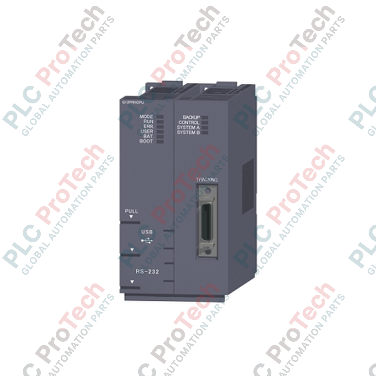
Direka untuk memastikan kawalan ketersediaan tinggi dalam persekitaran automasi kritikal, Mitsubishi Electric Q12PRHCPU beroperasi sebagai modul CPU redundan berprestasi tinggi dalam platform Siri MELSEC Q. Modul ini direka untuk mengelakkan masa henti sistem dengan menggunakan arkitektur redundan berganda di mana CPU sandaran segera mengambil alih kawalan sekiranya CPU utama gagal. Ia mempunyai kapasiti program sebanyak 120k langkah dan menyokong sehingga 4096 titik I/O fizikal, menjadikannya sesuai untuk operasi industri berskala besar dan tahan kesilapan.
Ciri Utama
-
Arkitektur Sistem Redundan: Menyokong redundansi hot-standby dengan pertukaran automatik tanpa gangguan untuk mengelakkan gangguan proses.
-
Pemprosesan Berkelajuan Tinggi: Menyampaikan kelajuan pelaksanaan arahan LD sebanyak 34 nanosaat (0.034 mikro saat) untuk pelaksanaan tugas yang pantas.
-
Kebolehan Hot-Swappable: Membolehkan penggantian modul dalam talian bagi CPU sandaran, bekalan kuasa, dan modul rangkaian tanpa menghentikan proses kawalan aktif.
-
Antara Muka Pengaturcaraan Berganda: Dilengkapi dengan port USB (Mini-B) dan RS-232 (Mini-DIN) untuk pengaturcaraan, diagnostik, dan pemantauan yang fleksibel.
-
Kapasiti Memori Luas: Menyediakan 120k langkah memori program bersama memori penjejakan khusus untuk penyelarasan data lancar antara unit aktif dan sandaran.
Aplikasi
- Rawatan air dan loji pemprosesan air sisa perbandaran.
- Barisan pemprosesan kimia, petrokimia, dan farmaseutikal berterusan.
- Penjanaan kuasa, automasi stesen janakuasa, dan rangkaian pengedaran utiliti.
- Pengudaraan terowong, sistem kuasa pengangkutan awam, dan infrastruktur kritikal.
Spesifikasi Teknikal
| Parameter |
Nilai Spesifikasi |
| Pengilang |
Mitsubishi Electric |
| Nombor Model |
Q12PRHCPU |
| Siri |
Siri MELSEC Q |
| Jenis Modul |
Modul CPU PLC Redundan |
| Kapasiti Program |
120k langkah (480 KB) |
| Titik I/O (Fizikal) |
4096 titik |
| Titik I/O (Peranti) |
8192 titik |
| Kelajuan Arahan LD |
0.034 mikro saat (34 ns) |
| Penggunaan Arus (5 VDC) |
0.89 A |
| Suhu Operasi |
0 hingga 55 darjahC |
| Suhu Penyimpanan |
-25 hingga 75 darjahC |
| Kelembapan Relatif |
5 hingga 95% RH (tidak mengembun) |
| Berat Bersih |
0.30 kg |
| Berat Penghantaran (Dikira) |
2.00 kg |
| Dimensi (W x H x D) |
27.4 mm x 98 mm x 115 mm |
| Negara Asal |
Jepun |
Sambungan dan Antara Muka
| Port Antara Muka |
Jenis Penyambung |
Penugasan Fungsi |
| Port RS-232 |
Mini-DIN 6-Pin |
Pengaturcaraan serial, sambungan periferal, dan diagnostik sistem. |
| Port USB |
Mini-B |
Pengaturcaraan, pemantauan, dan konfigurasi parameter berkelajuan tinggi melalui GX Works2. |
| Port Penjejakan |
Penyambung Redundan Khusus |
Sambungan kabel penjejakan berkelajuan tinggi untuk menyegerakkan memori dengan CPU sandaran. |
Wawasan Kejuruteraan Empirik
Model Alternatif & Keserasian
Q12PRHCPU mesti digunakan bersama unit asas redundan (seperti Q38RB atau Q68RB) dan modul bekalan kuasa redundan (Q61P-D). Ia tidak boleh dicampur dengan CPU siri Q standard pada unit asas standard untuk operasi redundan. Apabila menggantikan modul Q12HCPU lama, perhatikan bahawa unit asas bukan redundan standard tidak serasi dengan antara muka penjejakan fizikal dan laluan bas berganda siri redundan.
Perangkap Aplikasi & Nota Kejuruteraan
Panjang kabel penjejakan adalah had kritikal. Kabel penjejakan standard (QC10TR atau QC30TR) terhad kepada 3 meter. Melebihi jarak ini atau menggunakan kabel khusus tanpa pelindung boleh menyebabkan gangguan elektromagnetik, mengakibatkan kegagalan penyegerakan penjejakan (seperti "SP.UNIT LAY. ERR" atau "CONTROL CPU ERROR"). Selain itu, optimakan tetapan saiz data penjejakan dalam GX Works2 untuk mengelakkan lanjutan masa imbasan yang berlebihan semasa kitaran penyegerakan.
Petua Pengujian & Penyambungan
Sebelum menghidupkan sistem redundan, sahkan bahawa kedua-dua modul CPU utama (Sistem A) dan sandaran (Sistem B) mempunyai versi firmware yang sama. Perbezaan firmware boleh menghalang CPU sandaran daripada memasuki keadaan "BACKUP", menyebabkan sistem beroperasi dalam mod satu CPU tanpa redundansi. Sentiasa muat turun fail parameter dan blok program yang sama ke kedua-dua unit sebelum melaksanakan penyegerakan sistem awal.
Garis Panduan Pemasangan
AMARAN KRITIKAL:
Pastikan semua sumber kuasa luaran yang membekalkan unit asas dan rak I/O berkaitan dimatikan sepenuhnya sebelum memasang atau mengeluarkan modul CPU. Kegagalan mengasingkan kuasa boleh menyebabkan percikan elektrik, kerosakan pada bas belakang dalaman, atau perubahan keadaan sistem kawalan yang tidak dijangka.
1
Pasang modul CPU dengan kukuh pada unit asas redundan (Q38RB atau Q68RB), pastikan tab kunci bawah mengklik dengan kuat ke tempatnya.
2
Sambungkan kabel penjejakan khusus antara port penjejakan dua modul Q12PRHCPU untuk mewujudkan pautan penyegerakan.
3
Kencangkan penyambung kabel penjejakan menggunakan skru penahan terbina dalam untuk mengelakkan sambungan terputus secara tidak sengaja akibat getaran panel.
4
Bina sambungan tanah fungsi yang kukuh dari terminal LG dan FG unit asas ke bas tanah kabinet kawalan utama.