Description
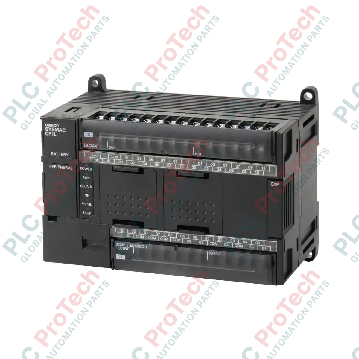
Engineered to deliver high-performance control within a compact form factor, the Omron CP1L-M40DR-A programmable logic controller coordinates robust local I/O handling and high-speed processing for demanding industrial automation architectures. This CPU unit features 40 built-in I/O points, incorporating 24 VDC inputs and rugged relay outputs designed to handle diverse switching loads. Operating on an AC power supply, it offers an optimal processing platform for small-to-medium machinery, supporting up to 10K steps of program capacity and advanced instruction execution times down to 0.55 microseconds.
Features
-
High-Capacity Memory: Equipped with a 10K-step program capacity and 32K words of data memory for complex logic execution.
-
High-Speed Counters: Built-in 4-axis high-speed counter inputs (up to 100 kHz) for precise positioning and rotary encoder feedback.
-
Robust Relay Outputs: Provides 16 electrical relay outputs to switch external actuator currents directly without auxiliary relays.
-
Flexible Expansion: Supports up to 3 CP-series expansion units or expansion I/O units, allowing a maximum system scale of 160 I/O points.
-
Integrated USB Port: Features a standard USB programming port for rapid configuration, diagnostic testing, and system commissioning.
Applications
-
Packaging Machinery: Controls high-speed wrapping, cartoning, and sealing cycles.
-
Conveyor and Material Handling: Sorts, diverts, and tracks products along dynamic manufacturing lines.
-
Pumping and HVAC Systems: Manages pressure levels, sequencing, and environmental controls.
-
Assembly Automation: Coordinates pneumatic actuators, sensors, and basic pick-and-place mechanisms.
Technical Specifications
| Parameter |
Specification |
| Manufacturer |
Omron |
| Model Number |
CP1L-M40DR-A |
| Series |
CP1L |
| Power Supply Voltage |
100 to 240 VAC, 50/60 Hz |
| Built-In Input Points |
24 points (24 VDC) |
| Built-In Output Points |
16 points (Relay) |
| Program Capacity |
10K steps |
| Instruction Execution Time |
0.55 microseconds (basic instructions) |
| High-Speed Counters |
100 kHz, 4 axes |
| Control Method |
Stored Program Method |
| I/O Control Method |
Cyclic scan with immediate refreshing |
| Shipping Weight (Calculated) |
3.00 kg |
| Package Dimensions (Calculated) |
160 mm x 120 mm x 110 mm |
Connections and Interfaces
| Terminal / Interface |
Function / Assignment |
| L1, L2/N |
AC Power Supply Input (100 to 240 VAC) |
| COM (Input) |
Common terminals for digital inputs (supports NPN or PNP wiring) |
| CIO 0.00 to CIO 0.11 |
High-speed input terminals for digital sensors and pulse encoders |
| CIO 100.00 to CIO 100.07 |
Relay output terminals, block-isolated |
| USB Port |
Type-B USB port for programming and online debugging via CX-Programmer |
Empirical Engineering Insights
Alternative Models & Compatibility
The CP1L-M40DR-A serves as a direct upgrade path for older legacy CPM2A-40CDR-A controllers. Note that while programming structures transfer smoothly through CX-Programmer, the physical dimensions and terminal positions differ, requiring panel layout adjustments. Unlike the "EM" or "EL" variants, this "M" type does not feature an onboard Ethernet port. If network-level integration is required, you must install an optional CP1W-CIF41 Ethernet card in one of the available option board slots.
Application Pitfalls & Engineering Notes
Because this CPU incorporates mechanical relay outputs, rapid switching profiles (such as PWM control or high-frequency cycling) will lead to premature contact wear. For high-speed or highly repetitive switching tasks, select a transistor output CPU (e.g., CP1L-M40DT-D). Additionally, when switching inductive loads such as solenoid valves, always install external surge suppressors or diodes to prevent back-EMF noise from interfering with the internal PLC logic.
Commissioning & Wiring Tips
To maintain high signal-to-noise ratios on the 100 kHz high-speed counter inputs, run the input cabling through a separate, grounded metallic conduit away from high-voltage AC lines. Ensure that the protective earth (PE) terminal on the AC power supply block is connected directly to a low-resistance copper grounding bar. Keep CX-Programmer updated to version 9.0 or higher to guarantee seamless block definition uploads.
Installation Guidelines
CRITICAL WARNING
Isolate and lock out all AC power sources before attempting physical installation, wiring, or module removal. Failure to de-energize the main line can cause severe electrical shock, circuit destruction, or erratic machine startup behavior.
1
Mount the CP1L CPU unit securely onto a standard 35 mm DIN rail inside an IP54 or higher industrial enclosure.
2
Connect the 100 to 240 VAC power source to the L1 and L2/N terminals using 1.25 mm2 (AWG 16) or larger copper wire.
3
Wire your field input sensors to the terminal block, matching the NPN/PNP common reference configuration chosen.
4
Attach your external loads to the relay output terminals, verifying that the current draw remains within the specified contact limits.