Description
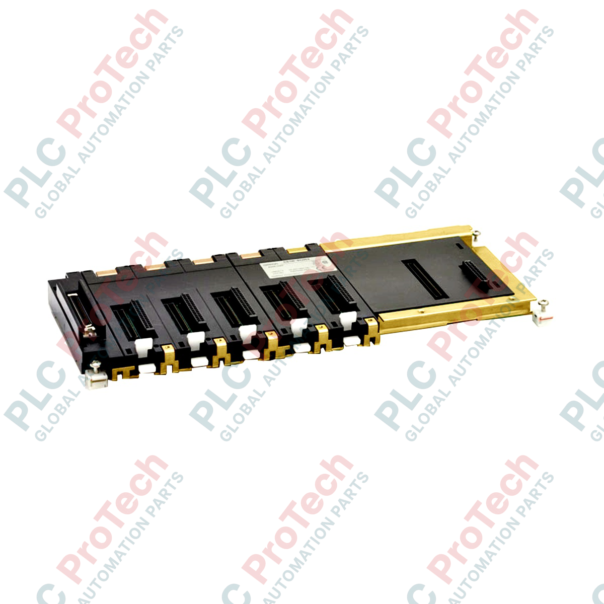
Serving as the hardware foundation of the modular control architecture, the Omron CS1W-BC053 provides the necessary physical mounting and high-speed electrical backplane bus for CS1-series programmable logic controller systems. This 5-slot CPU backplane enables reliable communication and regulated power distribution between the central processing unit, the system power supply module, and up to five local I/O or specialized application units.
Constructed to withstand harsh industrial environments, the Omron CS1W-BC053 ensures signal integrity across all processing channels. Its integrated expansion bus connector facilitates straightforward linkage to expansion backplanes, allowing the control system to scale effectively without compromising bus speed or data throughput.
Key Features
-
Five Dedicated I/O Slots: Accommodates up to 5 standard I/O, special I/O, or CPU bus units.
-
Dedicated CPU and Power Slots: Integrated slot positioning optimized for CS1G/CS1H CPUs and companion power supply modules.
-
Expansion Bus Interface: Built-in port for direct connection to CS1W-BI series expansion racks via standard expansion cables.
-
Rigid Mechanical Construction: Heavy-gauge chassis designed to resist torsional stress and vibration in control panels.
-
High-Speed Communication Bus: Low-latency parallel bus architecture ensures fast update cycles for dense I/O configurations.
Applications
-
Centralized Factory Automation: Houses process control systems for automotive assembly, material handling, and packaging machinery.
-
Water and Wastewater Processing: Serves as the robust central rack for localized telemetry, pumps, and treatment controllers.
-
Power Plant Auxiliary Controls: Reliable platform for non-safety-critical balance of plant (BOP) monitoring and sequencing systems.
-
HVAC and Environmental Control: Direct management of large-scale industrial chilling, heating, and air filtration plants.
Technical Specifications
| Parameter |
Specification |
| Manufacturer |
Omron |
| Model Number |
CS1W-BC053 |
| Product Series |
CS1 Series (CS1G / CS1H) |
| Backplane Type |
CPU Backplane |
| Number of I/O Slots |
5 slots (excluding CPU and Power Supply slots) |
| Power Supply Slot |
1 (Requires CS1 Series Power Supply Module) |
| CPU Slot Compatibility |
CS1G-CPU, CS1H-CPU |
| Expansion Capability |
Supported (via standard CS1W expansion bus connector) |
| Mounting Method |
M4 screws (panel mounting) or DIN rail via optional mounting brackets |
| Operating Temperature |
0 to 55 degC |
| Net Dimensions (W x H x D) |
294 mm x 130 mm x 80 mm |
| Shipping Weight (Calculated) |
1.0 kg |
| Package Dimensions (Calculated) |
320 mm x 160 mm x 110 mm |
Empirical Engineering Insights
Alternative Models & Compatibility
While the CS1W-BC053 is the standard 5-slot CPU backplane, environments requiring more spatial flexibility can scale to the 8-slot (CS1W-BC083) or 10-slot (CS1W-BC103) variants. Note that standard CS1W-BC backplanes are built for simplex systems; they cannot be substituted for CS1D-BC duplex backplanes when configuring hot-standby redundant CPU systems.
Application Pitfalls & Engineering Notes
Engineers must calculate the total current consumption of all proposed modules (CPU, special I/O, communication cards, and standard I/O) against the output power limits of the mounted power supply module. Ensure that both the 5V DC and 26V DC limits are not breached, particularly when utilizing high-density analog modules or network communication cards on the 5-slot bus.
Commissioning & Wiring Tips
To mitigate electrical noise, ensure that the functional ground (FG) and protective ground (GR) terminals of the mounted power supply module are wired directly to a low-resistance earth ground point using heavy-gauge wire (minimum 2 mm squared). Failure to ground the system adequately can result in communication dropouts or transient bus faults across the backplane slots.
Installation Guidelines
CRITICAL WARNING
Disconnect all primary and auxiliary AC/DC power sources feeding the control panel prior to mounting, removing, or wiring any modules onto the CS1W-BC053 backplane. Failure to completely de-energize the system can result in severe electric shock, permanent damage to the CPU backplane contacts, or processor fault states.
1
Mechanical Mounting: Securely bolt the backplane to the control panel backplate using M4 screws in the designated mounting holes. Ensure the mounting plate is clean, flat, and free of paint at the ground contact points to ensure optimal grounding.
2
Power Supply Assembly: Insert the Omron power supply module into the leftmost designated power slot and secure it with its integrated locking mechanisms and terminal screws.
3
CPU and Module Allocation: Slide the CS1 CPU module into the slot adjacent to the power supply. Install subsequent I/O and communication modules into slots 0 through 4, making sure that each module clicks firmly into position and its locking levers are fully engaged.
4
Bus Expansion Configuration: If expanding to secondary racks, remove the protective cover from the expansion connector on the right side of the backplane and firmly seat the CS1W-CN expansion cable, tightening the securing screws.