Description
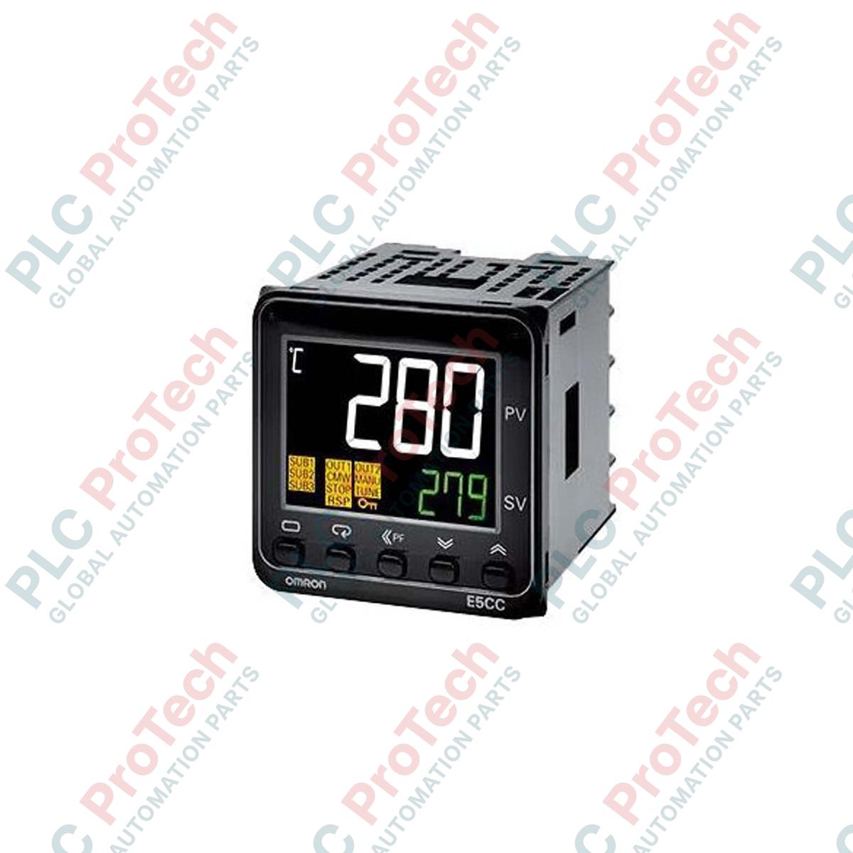
Designed for highly precise thermal process regulation, the Omron E5CC-RX2ADM-800 digital temperature controller delivers advanced PID control within a compact 48x48 mm (1/16 DIN) form factor. This instrument features a high-contrast white LCD display with 15.2 mm character heights, ensuring maximum legibility in high-density control panels. Operating on a 24 VAC/VDC auxiliary power supply, the unit integrates 2-PID control logic with automatic tuning to minimize overshoot and stabilize temperature fluctuations in demanding thermal systems. Built with a relay control output and dual auxiliary outputs, this hardware is engineered for direct integration into industrial machines, packaging lines, and environmental chambers.
Features
-
Universal Sensor Input: Direct support for multi-range thermocouples, platinum resistance thermometers (RTDs), and analog current/voltage inputs.
-
Dual Auxiliary Relays: Two independent auxiliary relay outputs for alarms, limit controls, or system interlocks.
-
Advanced Control Algorithms: High-speed sampling loop of 50 ms combined with 2-PID control and auto-tuning (AT) capabilities.
-
Enhanced Visibility: Large, easy-to-read white PV display segment contrasted against a dark background.
-
Compact Depth: Only 60 mm depth behind the panel, minimizing enclosure footprint and maximizing wiring space.
Applications
-
Plastic Extrusion & Molding: Accurate barrel zone heating control and die temperature stabilization.
-
Packaging Machinery: Precise sealing bar temperature management to ensure consistent package integrity.
-
Industrial Ovens & Furnaces: High-reliability thermal profiling and multi-stage heating curve regulation.
-
Food & Beverage Processing: Sanitation-compliant temperature monitoring and pasteurization loop control.
Technical Specifications Table
| Parameter |
Specification Value |
| Manufacturer |
Omron |
| Model Code |
E5CC-RX2ADM-800 |
| Supply Voltage |
24 VAC (50/60 Hz) / 24 VDC |
| Operating Voltage Range |
85% to 110% of rated supply voltage |
| Power Consumption |
Max 4.1 VA (24 VAC) / Max 2.3 W (24 VDC) |
| Control Output 1 |
Relay output (SPST-NO, 250 VAC, 3 A resistive load) |
| Auxiliary Outputs |
2 Relay outputs (SPST-NO, 250 VAC, 3 A resistive load) |
| Control Method |
ON/OFF control or 2-PID control (with auto-tuning) |
| Sampling Period |
50 ms |
| Terminal Connection Type |
Screw terminal block (M3) |
| Front Panel Dimensions |
48 x 48 mm |
| Operating Ambient Temp |
-10 to 55 degC (with no condensation or icing) |
| Shipping Weight (Calculated) |
0.35 kg |
| Package Dimensions (Calculated) |
110 mm x 65 mm x 65 mm |
Empirical Engineering Insights
Alternative Models & Compatibility
The E5CC-RX2ADM-800 serves as a direct functional replacement for legacy models such as the E5CN-R2MD-500 series. However, when migrating to the E5CC platform, verify the wiring terminations: the E5CC uses a different physical pin layout relative to older generations. If your application relies on voltage pulse output for solid-state relays (SSRs), do not use the RX model; select the E5CC-QX2ADM-800 instead to prevent damage to the relay mechanism caused by high-frequency switching.
Application Pitfalls & Engineering Notes
Because this model is rated for 24 VAC/VDC power, it is highly sensitive to voltage drops along long DC distribution lines in control panels. Ensure that the power supply is situated close to the instrument and is isolated from heavy inductive switching devices. Running auxiliary outputs with high-current AC loads near their 3 A limit without RC snubbers will significantly shorten the electrical lifespan of the internal output relays due to contact arcing.
Commissioning & Wiring Tips
To configure parameters prior to cabinet powering, use the Omron CX-Thermo software paired with the front-panel setup port interface. This approach allows parameter configuration over a USB bus power connection, completely eliminating the need to connect 24V field power during the engineering phase. Ensure that you ground the analog shield wire of the sensor close to the panel entry point rather than routing it alongside high-voltage AC cables.
Installation Guidelines
CRITICAL WARNING: Prior to attempting physical installation, mounting, or terminal wiring, ensure that the primary electrical power source to the control cabinet is completely de-energized. Confirm the absence of residual AC/DC voltages using a calibrated digital multimeter. Failure to isolate power may cause electrical shock, physical hazard, or permanent failure of the internal logic circuits.
1
Insert the controller housing through the prepared 45x45 mm panel cutout from the front, ensuring the protective rubber gasket is correctly seated to maintain the IP66 water-resistant seal.
2
Slide the plastic mounting adapter from the rear of the panel along the controller body until the adapter clicks firmly against the panel backplate. Tighten the securing screws evenly to prevent frame distortion.
3
Terminate the universal input lines (thermocouple or RTD) using high-quality insulated crimp lugs to avoid signal noise. Route power and control output wires along dedicated low-voltage wireways separated from motor drive leads.