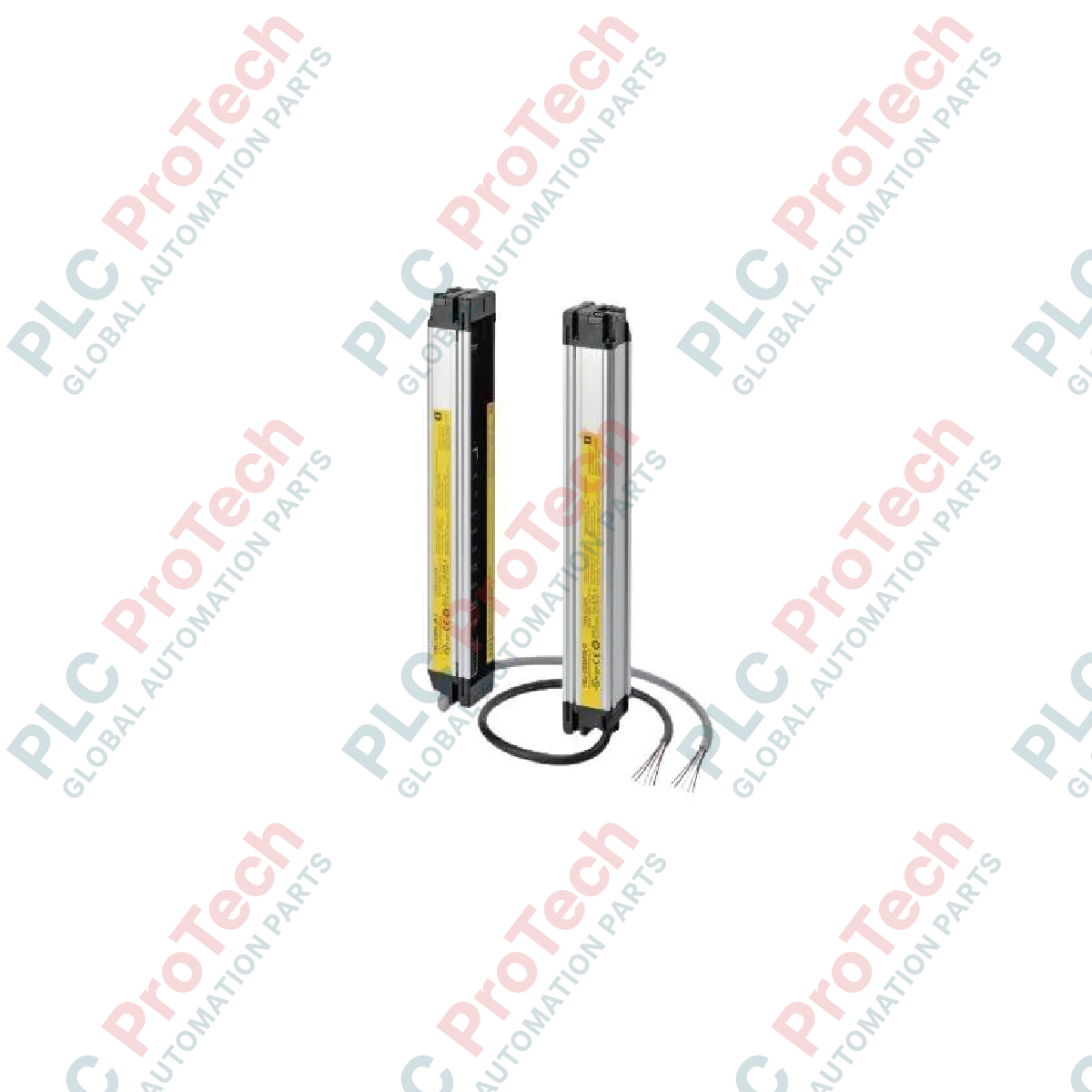
Description
Providing hand and arm protection within machine safeguarding architectures, the Omron F3SJ-E0385N25 optoelectronic safety barrier is engineered for high-reliability industrial detection. This Type 4 safety light curtain features an 18-beam configuration with a 25-mm resolution (detection capability), making it ideal for point-of-operation safeguarding. Operating on NPN logic, it integrates seamlessly into control systems requiring sinking safety outputs, while its IP65 housing offers robust defense against dust and water jets in demanding factory environments.
Features
-
Type 4 Safety Rating: Compliant with international safety standards for advanced personnel protection.
-
Optimal Detection: 18 infrared beams with a 20-mm beam pitch, achieving a reliable 25-mm detection capability.
-
NPN Safety Outputs: Dual solid-state outputs designed for interface with NPN-compatible safety control systems.
-
Compact Housing: Reduced cross-section dimensions allow for seamless mechanical integration inside tight machine frames.
-
Robust Sealed Enclosure: Rated to IP65 to withstand washdowns and particulate contamination.
Applications
- Guarding of assembly lines and automated pinch points.
- Safeguarding of light-duty packaging machinery and wrapping stations.
- Access control and robotic workstation perimeter monitoring.
- Material handling and conveyor sorting hazard zone protection.
Technical Specifications
| Parameter |
Specification Value |
| Manufacturer |
Omron |
| Model Number |
F3SJ-E0385N25 |
| Sensor Type |
Type 4 Safety Light Curtain |
| Output Type |
NPN |
| Number of Beams |
18 |
| Protective Height |
385 mm |
| Detection Capability |
25-mm diameter |
| Beam Gap (Pitch) |
20 mm |
| Operating Range |
0.2 to 7.0 m |
| Power Supply Voltage |
24 VDC +/-20% (SELV/PELV, ripple p-p 10% max.) |
| Current Consumption (Emitter) |
41 mA max. |
| Current Consumption (Receiver) |
40 mA max. |
| Light Source |
Infrared LED (870 nm) |
| IP Rating |
IP65 |
| Net Weight |
1.5 kg |
| Shipping Weight (Calculated) |
3.0 kg |
Empirical Engineering Insights
Alternative Models & Compatibility: The F3SJ-E (Easy) series is optimized for straightforward on/off safeguarding without auxiliary functions. If your application requires cascading (series connection of multiple light curtains), blanking, or muting functionalities, you must transition to the F3SJ-B (Basic) or F3SJ-A (Advanced) series, as these features are physically absent in the F3SJ-E firmware and hardware profile.
Application Pitfalls & Engineering Notes: Because the F3SJ-E0385N25 features NPN outputs, it is critical to verify the input configuration of your safety controller. Interfacing an NPN safety light curtain with a PNP-only safety input card will result in an unresolvable diagnostic fault, preventing the safety circuit from resetting. Additionally, ensure your power supply meets the SELV/PELV requirement to avoid common-mode noise issues that can trigger false optical faults.
Commissioning & Wiring Tips: During on-site commissioning, route the synchronization line away from high-power AC cables or variable frequency drives (VFDs). Electro-magnetic interference on the synchronization path can cause transient synchronization dropouts, resulting in the receiver flashing its error indicators even when the optical path is mechanically aligned and clear.
Installation Guidelines
CRITICAL SAFETY WARNING: Before starting any physical mounting, electrical installation, or maintenance, confirm all power supplies feeding the hazard area and safety system are locked out and tagged out (LOTO). Verify zero voltage status with a certified multimeter. Failure to isolate power can result in electric shock or accidental machine start-up.
1
Mount the Emitter and Receiver units parallel to each other on a rigid, vibration-damping structure, ensuring that the detection zone completely covers the defined hazardous area.
2
Wire the connectors according to the NPN wiring diagrams, ensuring the 0V common and +24 VDC SELV/PELV lines are properly terminated and shielded from electrical noise.
3
Apply power and verify that the optical alignment indicators on both the Emitter and Receiver transition to a stable green state, indicating optimal optical path alignment.
4
Conduct a mandatory trip test by slowly passing a 25-mm test rod through the top, middle, and bottom of the active sensing field to confirm reliable OSSD output interruption.