1 z 3

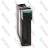
Allen-Bradley 1771-OB PLC-5 Digital DC Output Module

Allen-Bradley 1771-OB PLC-5 Digital DC Output Module

Only 8 item(s) left in stock
  • Manufacturer: Allen-Bradley

  • Product No.: 1771-OB

  • Country of origin:Stany Zjednoczone

  • Product Type: Digital Output Module

  • Barcode: 8537101190

  • Payment: T/T, Western Union

  • Weight: 900g

  • Dimensions: 3.5cm x 13cm x 14.5cm

  • Shipping port: Xiamen

  • Warranty: 12 months

Ilość
Pokaż kompletne dane

The 1771-OB is an 8-channel digital solid-state electronic device engineered for the PLC-5 / 1771 I/O Platform to drive low-voltage direct current industrial control hardware. It provides electrical switching paths for various field components, including DC motor drivers, status indicators, and industrial solenoid valves. The internal control micro-logic is energized via the local I/O chassis backplane rail, drawing a maximum current of 165 mA to maintain structural optoelectronic isolation between high-level plant field elements and core processor busses. System integration is established through the standard 1771-WA wiring arm connector assembly, permitting physical hot-swapping or card replacement sequences without disturbing landed field terminal connections.

Features

  • High-Density Output Distribution: Integrates eight independent solid-state DC switching circuits within a single-slot chassis package.
  • Dedicated Short-Circuit Protection: Individual 2 A, 8AG protective fuses mounted per channel safeguard the module against severe field overcurrent hazards.
  • Visual Status Array: Equipped with nine front-panel diagnostic LEDs providing localized visualization of blown-fuse status and specific channel conduction states.
  • Direct Input Interlocking: Supports zero-potential ground reference looping to directly drive discrete DC input modules, such as the 1771-IB receiver block.
  • Optoelectronic Backplane Protection: Incorporates continuous 1500 Vca (rms) galvanic isolation to prevent destructive external voltage transients from damaging backplane control logic.
  • Mechanical Slot Keying: Backplane socket keying fields restrict module slot alignment, ensuring only matched electrical module types sit within defined wiring nests.

Applications

  • Distributed control of factory floor solenoid-actuated pneumatic manifolds.
  • Direct activation of low-current DC motor speed control enable drives.
  • Remote instrumentation control panels and pilot lamp illumination matrix lines.
  • Inter-rack logic interlocking with low-voltage input hardware sub-assemblies.

Hardware Specifications

Parameter Specification
Manufacturer Allen-Bradley / Rockwell Automation
Model 1771-OB
Product Series PLC-5 / 1771 I/O
Module Type Digital DC Output Driver Module
Outputs Per Module 8
Chassis Compatibility 1771 I/O Chassis
Input Operational Voltage Range 10 Vdc to 27 Vdc
Output Current Capacity 1.5 A per individual output (not to exceed 8 A total per module)
Maximum Current Surge 4 A for 1 ms, repeatable at 1 s intervals
Off-State Leakage Current 1 mA maximum per output
On-State Voltage Drop 2 Vdc maximum
Signal Transmission Delay 10 ms (On to Off and Off to On states)
Power Dissipation 0.9 Watts minimum, 16.9 Watts maximum
Thermal Dissipation 3.0 BTU/h minimum, 57.6 BTU/h maximum
Backplane Logic Current Demand 165 mA @ 5 Vdc plus/minus 5%
Optoelectric Isolation 1500 Vca (rms)
Operating Temperature Range 0 degC to 60 degC
Storage Temperature Range -40 degC to 85 degC
Relative Ambient Humidity 5% to 95% (non-condensing)
Field Wiring Specifications Flexible cable with 1.5 mm2 nominal cross-section
Backplane Plastic Keying Slots Between positions 4 and 6, and between positions 18 and 20
Internal Fusing 2 A, 8AG rating (one individual fuse per output path)
Terminal Connection Block 1771-WA Wiring Arm

Connections/Interfaces

Connector Terminal Pin Function
Terminal A +DC Voltage Supply Input Reference
Terminal 0 Digital Output Channel 0 Signal Line
Terminal 1 Digital Output Channel 1 Signal Line
Terminal 2 Digital Output Channel 2 Signal Line
Terminal 3 Digital Output Channel 3 Signal Line
Terminal 4 Digital Output Channel 4 Signal Line
Terminal 5 Digital Output Channel 5 Signal Line
Terminal 6 Digital Output Channel 6 Signal Line
Terminal 7 Digital Output Channel 7 Signal Line
Terminal B DC Common Ground Return Reference

Engineering Notes

  • Terminal to Bit Discrepancy: The terminal channel designations etched on the physical 1771-WA wiring arm hardware do not directly map to software internal image register data bits. Refer strictly to the system allocation table when building control code.
  • Potential Equalization: When cross-linking an output channel directly into an input processing unit (such as a 1771-IB), a common power supply loop must feed both blocks to tie all reference grounds to an identical voltage potential.
  • Polarity Critical Warning: Correct structural polarity must be maintained on all direct current power terminals. Applying alternating current (AC) power configurations or cross-wiring polarity rails will result in critical module hardware destruction.
  • Backplane Power Balancing: The 165 mA backplane current consumption must be calculated into the aggregate power supply capacity budget of the specific 1771 chassis rack to avoid thermal overloading or backplane dip errors.

Field Guidelines

  • Electrostatic Grounding Procedures: Operators must latch an approved ESD wrist grounding strap to a structural physical ground point or discharge local potentials by touching an earth-grounded steel frame before touching card edges.
  • Plastic Keying Installation: Ensure the chassis backplane keying pegs are properly seated at the factory positions (between pins 4/6 and pins 18/20) to prevent the accidental insertion of mismatched voltage cards.
  • Chassis De-energization: Complete chassis rack power downcycles are required prior to sliding the driver module out of its physical slot to protect operators and prevent inductive backplane transients.
  • Fuse Extraction Protocol: To safely swap a compromised fuse assembly, release the front mechanical swing arm latch, withdraw the board housing, undo the two case retention screws, and replace the spent 2 A, 8AG component inside.

Technical & Procurement FAQ

Q: What specific fuse replacement specification must be used if a channel drops out? A: Each individual output switch is paired with a standard 2 A, 8AG form-factor fuse accessible underneath the card side cover.

Q: Can this DC driver module be safely slotted into the leftmost slot of a 1771 chassis? A: No, the far-left slot of the 1771 chassis configuration is structurally reserved for the master processor module or remote I/O network adapter head.

Q: Does the module display indicators on the front face for individual circuit diagnostics? A: Yes, it features one dedicated red LED for blown fuse notification alongside eight individual red status LEDs that light up when an output channel is actively energized.

Globalna ekspresowa wysyłka

  • Standardowa dostawa: 4-6 dni roboczych za pośrednictwem DHL, FedEx i UPS.
  • Ekspresowa wysyłka: Wysyłka tego samego dnia dla zamówień dostępnych w magazynie złożonych przed godziną 14:00 (GMT+8).
  • Globalne pokrycie: Obsługujemy ponad 150 krajów, w tym szybką dostawę do Arabii Saudyjskiej i ZEA.

Zwroty i gwarancja

  • 30-dniowa gwarancja: Zwroty przyjmowane są dla produktów dostępnych w magazynie, w oryginalnym, fabrycznie zapieczętowanym opakowaniu.
  • 12-miesięczna gwarancja: Każdy komponent przemysłowy objęty jest naszą profesjonalną gwarancją techniczną.

Zamówienia są przetwarzane i dostarczane od poniedziałku do piątku (z wyłączeniem dni świątecznych).


Aby poznać pełne warunki kwalifikowalności, opłaty za przyjęcie towaru z powrotem oraz szczegóły dotyczące zwrotów międzynarodowych, prosimy zapoznać się z naszym oficjalnym Polityka zwrotów i zwrotu pieniędzy .

TECHNICAL SPECIFICATIONS

Color pattern
Czarny
Country of origin
Stany Zjednoczone
Power source
Zasilanie prądem stałym

Ostatnio oglądane produkty

Wiedza techniczna

Siłowniki elektryczne zaprojektowane do zastąpienia systemów hydraulicznych: praktyczny przewodnik po automatyce przemysłowej

Ten artykuł wyjaśnia, jak zintegrowane siłowniki elektryczne, takie jak seria e-Actuator firmy SMC, rewolucjonizują przemysłową kontrolę ruchu, zastępując tradycyjne systemy pneumatyczne i...

Operacje matematyczne z wykorzystaniem OpenPLC w zastosowaniach automatyki przemysłowej

Ten artykuł wyjaśnia, jak systemy PLC wykonują podstawowe operacje matematyczne, takie jak dodawanie, odejmowanie, mnożenie, dzielenie, modulo oraz potęgowanie w automatyce przemysłowej. Pokazuje,...

Zaawansowana logika boolowska w programowaniu PLC za pomocą FBD: praktyczne zastosowania przemysłowe wykraczające poza podstawową logikę

Artykuł wyjaśnia kilka zaawansowanych funkcji logiki boolowskiej stosowanych w programowaniu PLC, wykraczających poza podstawowe operacje AND, OR i NOT. Omawia, jak narzędzia takie jak tabele prawdy,...

Logika boolowska w programowaniu PLC: Zrozumienie bramek logicznych FBD

Logika boolowska jest podstawą każdego programu PLC. Od prostych sterowań maszyn po złożone systemy automatyki przemysłowej, bramki logiczne decydują o tym, jak sterowniki reagują na zmieniające się...

Szczegółowy przewodnik po przemysłowych zaporach sieciowych i segmentacji sieci OT

Przemysłowe zapory sieciowe odgrywają kluczową rolę w cyberbezpieczeństwie OT, chroniąc sieci PLC, DCS i SCADA poprzez segmentację, kontrolę ruchu przychodzącego/wychodzącego oraz integrację IDS/IPS...

Przewodnik po chwytakach robotycznych: od delikatnego manipulowania po ciężką automatykę

Nowoczesne chwytaki robotyczne ewoluują poza tradycyjne mechaniczne szczęki. Od systemów adhezyjnych inspirowanych gekonem i miękkich chwytaków spożywczych po narzędzia magazynowe zasilane sztuczną...