


Wymiana Yokogawa AAI835: sprawdzenie okablowania i barier przed wymianą
Przed wymianą Yokogawa AAI835 sprawdź mapę kanałów 4 wejścia/4 wyjścia, zachowanie pętli przy utracie zasilania, typ bariery, obciążenie wyjścia, kabel i redundancję.
Manufacturer: General Electric
Product No.: IC695PSA040
Country of origin:Stany Zjednoczone
Product Type: Zasilacz
Barcode: 8537101190
Payment: T/T, Western Union
Weight: 1200g
Dimensions: 3,5 cm x 13 cm x 13,5 cm
Shipping port: Xiamen
Warranty: 12 months
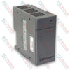
IC695PSA040 (IC695PSA040) to wysokowydajny, 40-watowy moduł zasilacza zaprojektowany dla platformy GE PACSystems RX3i. Moduł działa z uniwersalnym zakresem napięcia wejściowego od 85 do 264 VAC lub od 100 do 300 VDC i zapewnia stabilną dystrybucję zasilania bezpośrednio przez płytę montażową, zasilając lokalne zasoby przetwarzania i wejść/wyjść. Zakłady uzdatniania wody, instalacje przetwarzania chemicznego oraz linie montażowe w zakładach produkcyjnych wykorzystują moduł IC695PSA040 (IC695PSA040) , aby zapewnić przewidywalne działanie sterownika przy wahaniach napięcia sieciowego. Moduł zasilacza odseparowuje wewnętrzną elektronikę kasety od zakłóceń elektrycznych pochodzących z obwodów zewnętrznych, rejestruje prognozowane usterki bezpośrednio w tabelach procesora podczas obciążenia termicznego lub elektrycznego oraz zapewnia zintegrowaną funkcję podtrzymania zasilania. Ta odporność architektoniczna zapobiega nagłym wyłączeniom sterownika PLC, chroni kluczowe parametry pracy i znacząco ogranicza kosztowne, nieplanowane przestoje zakładu.
Topologia sprzętowa modułu IC695PSA040 opiera się na lokalnym zarządzaniu wyjściami trzech szyn oraz automatycznej ochronie elektronicznej.
Trójtorowe wyjście napięciowe: Niezależnie dostarcza napięcia +5.1 VDC i +3.3 VDC, aby spełnić wymagania modułów systemu RX3i, a także udostępnia dedykowaną ścieżkę wyjściową przekaźnika +24 VDC do zasilania zewnętrznych modułów przekaźnikowych wyjść.
Aktywne zabezpieczenia nadprądowe: Wyposażony we wbudowane elektroniczne ograniczenie prądu, które ogranicza szynę 5.1 VDC do 7 A, a szynę 3.3 VDC do 10 A. W przypadku przeciążenia lub zwarcia zasilacz wyłącza się automatycznie i inicjuje ciągłe próby automatycznego ponownego uruchomienia do czasu usunięcia usterki w obwodzie zewnętrznym.
Kompleksowa diagnostyka stanu: Zawiera zestaw czterech czołowych diod LED sygnalizujących stan, połączonych z wewnętrznymi przekaźnikami diagnostycznymi, które przekazują w czasie rzeczywistym informacje o przegrzaniu, przeciążeniu i stanie wewnętrznych podzespołów bezpośrednio do centralnego rejestratora usterek procesora.
| Indeks inżynieryjny | Specyfikacja techniczna |
| Numer modelu | IC695PSA040 |
| Identyfikator marki | GE PACSystems (General Electric) |
| Seria systemu sterowania | Sterowniki RX3i |
| Łączna znamionowa moc wyjściowa | Maksymalnie 40 W łącznie |
| Nominalne parametry wejściowe | 120/240 VAC lub 125 VDC |
| Zakres wejściowego napięcia AC | 85 do 264 VAC |
| Zakres wejściowego napięcia DC | 100 do 300 VDC |
| Maksymalna moc wejściowa | Maksymalnie 70 W przy pełnym obciążeniu |
| Próg prądu rozruchowego | Maksymalnie 4 A przez 250 milisekund |
| Specyfikacja prądu wyjściowego | 5,1 VDC (0 do 6 A), 3,3 VDC (0 do 9 A), 24 VDC (0 do 1,6 A) |
| Granice napięcia | 5,1 VDC (5,0 do 5,2 VDC), 3,3 VDC (3,1 do 3,5 VDC), 24 VDC (19,2 do 28,8 VDC) |
| Izolacja galwaniczna | 250 VAC ciągle (1500 VAC przez 1 minutę, wejście do płyty montażowej) |
| Czas podtrzymania | Minimum 20 ms podczas przerwy w źródle zasilania |
| Zakres okablowania obiektowego | Pojedynczy przewód 14 AWG do 22 AWG na zacisk |
| Możliwość łączenia szeregowego | Do 4 jednostek PSA040 |
| Zakres temperatury powietrza roboczego | Od 0 do 60°C (temperatura otoczenia zewnętrznego) |
| Kod ochrony ATEX | II 3 G Ex nA IIC T3C |
| Kraj pochodzenia | Stany Zjednoczone |
Czy zasilacz IC695PSA040 można skonfigurować równolegle w celu uzyskania redundancji N+1?
Nie. Ten konkretny zasilacz jest przeznaczony wyłącznie do samodzielnej pracy w uniwersalnej płycie montażowej RX3i (seria katalogowa IC695). Nie można łączyć go z innymi zasilaczami w celu zwiększenia wydajności systemu ani zapewnienia redundancji sprzętowej. Próba uruchomienia starszych wersji (IC695PSA040C i wcześniejszych) wraz z innym zasilaczem w tej samej płycie montażowej może spowodować poważne uszkodzenie sprzętu.
Co powoduje zmianę koloru głównego wskaźnika LED zasilania ze stałego zielonego na bursztynowy?
Zielona kontrolka oznacza, że moduł jest zasilany i prawidłowo dostarcza stabilne napięcia stałe do płyty montażowej. Bursztynowa kontrolka wskazuje, że zasilanie wejściowe jest prawidłowo doprowadzone do zacisków wejściowych modułu, ale przełącznik na panelu przednim jest ustawiony w pozycji OFF, co uniemożliwia doprowadzanie zasilania do szafy.
Jakie podstawowe awarie systemowe powodują całkowite wyłączenie bez wyświetlenia zewnętrznego wskaźnika usterki LED?
W przewodzie wejściowym znajduje się nienaprawialne wewnętrzne zabezpieczenie topikowe, stanowiące ostateczne sprzętowe zabezpieczenie. Chociaż moduł zwykle uruchamia elektroniczne wyłączenie, zanim bezpiecznik ulegnie uszkodzeniu, skrajne zwarcie wewnętrznego elementu lub nadmierne wejściowe przepięcie może trwale przerwać to zabezpieczenie. Po przepaleniu bezpiecznika wszystkie wskaźniki działania gasną, a moduł wymaga fizycznej wymiany.
Ograniczanie ryzyka porażenia prądem i bezpieczne sterowanie włączaniem/wyłączaniem:
Podczas pracy z aktywnym źródłem zasilania AC na wewnętrznych strukturach obwodów modułu występują niebezpieczne napięcia (120 VAC lub 240 VAC). Podczas standardowej pracy przednie drzwiczki dostępu do zacisków muszą pozostać zamknięte, aby zapobiec śmiertelnemu porażeniu prądem. Należy pamiętać, że znajdujący się za drzwiczkami przedni przełącznik ON/OFF steruje wyłącznie stopniami wtórnego wyjścia DC; NIE odłącza on przewodów fazowych pod napięciem doprowadzających zasilanie do listew zaciskowych.
Wprowadzanie przewodów i ograniczenia momentu dokręcania:
Wszystkie przewody zacisków należy odizolować na długości od 9 mm do 11 mm. Upewnij się, że przewód jest całkowicie wsunięty do obudowy zacisku, tak aby izolacja przewodu przylegała do wewnętrznego ogranicznika izolacji. Ostrożnie dokręć zaciski śrubowe, nie przekraczając maksymalnego dopuszczalnego momentu dokręcania 0.5 N-m (4.4 inch-lbs). Nieprawidłowe wsunięcie może spowodować zaciśnięcie zacisku śrubowego na izolacji przewodu, prowadząc do przerw w obwodzie lub przegrzewania punktów zakończeń.
Procedura dotycząca zworki ochrony przed przepięciem i testowania Hi-pot:
Dolne listwy zaciskowe zawierają obwód przeciwprzepięciowy z warystorem z tlenku metalu (MOV), który musi być podłączony do uziemienia obudowy za pomocą zworki instalowanej przez użytkownika, aby zapewnić podstawową ochronę wejścia przed przepięciem. Aby przeprowadzić próbę dielektryczną wysokim napięciem (Hi-pot) zasilacza, należy wyłączyć ten obwód przeciwprzepięciowy, usuwając zworkę. Natychmiast po zakończeniu testu należy ponownie zamontować zworkę uziemiającą, aby przywrócić ochronę przed przepięciami przejściowymi.


Global Express Shipping
Returns & Warranty


| Product Image | Model Number / Title | Condition | Availability | Action |
|---|---|---|---|---|
|
Allen-Bradley 1746-P4 SLC 500 zasilacz | Original New | In Stock | View Details |
Globalna ekspresowa wysyłka
Zwroty i gwarancja
Zamówienia są przetwarzane i dostarczane od poniedziałku do piątku (z wyłączeniem dni świątecznych).
Aby poznać pełne warunki kwalifikowalności, opłaty za przyjęcie towaru z powrotem oraz szczegóły dotyczące zwrotów międzynarodowych, prosimy zapoznać się z naszym oficjalnym Polityka zwrotów i zwrotu pieniędzy .
| Color pattern |
Czarny
|
| Country of origin |
Stany Zjednoczone
|
| Power source |
Zasilany prądem zmiennym
|

Przed wymianą Yokogawa AAI835 sprawdź mapę kanałów 4 wejścia/4 wyjścia, zachowanie pętli przy utracie zasilania, typ bariery, obciążenie wyjścia, kabel i redundancję.

ABB PM891K01, artykuł 3BSE053241R1, to nieredundantny zestaw procesora AC 800M. Przed wymianą skorzystaj z tej listy kontrolnej.

Kontrole wymiany dla ABB TP853 3BSE018126R1: zidentyfikuj zainstalowany interfejs CI853, CI855, CI857 lub CI861, zapisz okablowanie i zweryfikuj komunikację po instalacji.

Weryfikacja parametrów technicznych sterownika Allen-Bradley 5069-L330ERMS2: możliwości sterownika, osobne zestawy RTB, limity lokalnych modułów I/O, limity liczby węzłów sieciowych oraz liczba osi...

Kontrole, które należy zapisać przed wymianą sterownika ABB 3HNE 00006-1 DSQC 351: generacja sterownika, okablowanie X3/X5/X20/X21, ustawienia DeviceNet, mapowanie INTERBUS oraz stany diod LED.

Porównaj modele IC693CPU360 i IC693CPU364 pod kątem interfejsu Ethernet, obciążenia +5 VDC, pamięci, limitów kasety oraz kontroli przed wymianą.