Opis
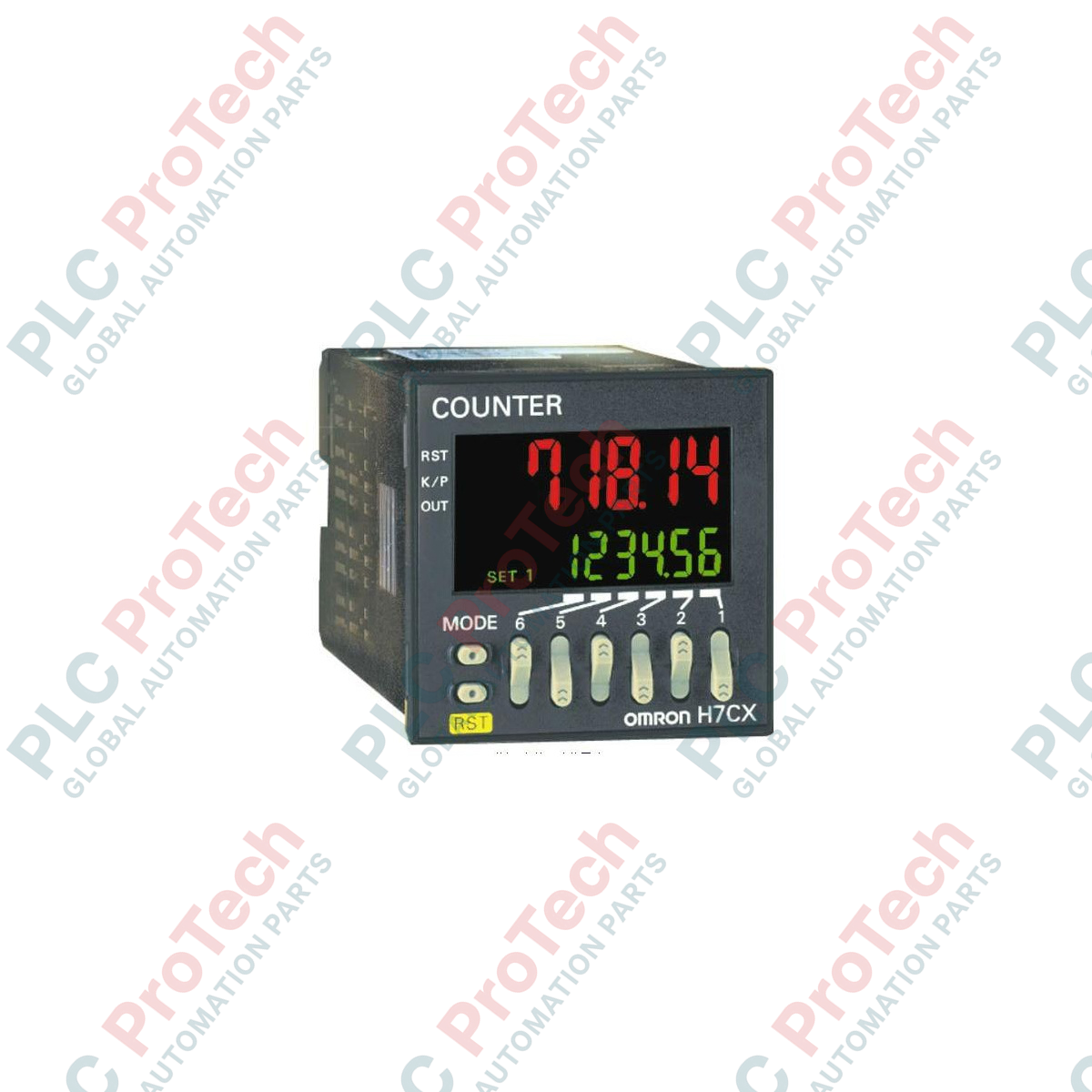
Bezproblemowo zintegrowany z nowoczesnymi liniami przetwórczymi Omron H7CX-A11D1-N działa jako precyzyjny licznik cyfrowy i tachometr w formacie 1/16 DIN, zaprojektowany do szybkiego monitorowania impulsów i koordynacji wyjść. Wyposażony w wyraźny, dwukolorowy wyświetlacz znaków PV, ten wielotrybowy sterownik umożliwia personelowi śledzenie liczby sztuk, partii i parametrów prędkości na jednym, kompaktowym panelu. Urządzenie obsługuje magistralę sterującą o wielu napięciach oraz integruje elastyczne ścieżki wyjściowe ze stykiem i półprzewodnikowe, aby bezpiecznie i niezawodnie sterować dodatkowymi procesami automatyzacji.
Najważniejsze cechy
-
6-cyfrowy wyświetlacz PV: Wyraźne znaki w kolorze czerwonym lub zielonym z możliwością konfiguracji do monitorowania procesu w czasie rzeczywistym.
-
Elastyczna praca wielotrybowa: Możliwość konfiguracji jako licznik jednostopniowy, licznik wsadowy, licznik sumujący, licznik podwójny lub tachometr cyfrowy.
-
Interfejs gniazda 11-stykowego: Umożliwia szybkie połączenie elektryczne, wymianę urządzenia oraz solidną integrację.
-
Hybrydowe konfiguracje wyjść: Jednoczesna dostępność wyjść ze stykiem fizycznym (SPDT) i wyjść tranzystorowych półprzewodnikowych (NPN/PNP).
-
Uniwersalne zasilanie niskonapięciowe: Kompatybilność zarówno z sieciami zasilania 12–24 VDC, jak i 24 VAC.
Zastosowania przemysłowe
- Szybkie pakowanie, sortowanie i objętościowe zliczanie kartonów.
- Monitorowanie prędkości maszyn wirujących i tachometryczny pomiar prędkości ciągłej linii.
- Systemy zliczania cykli procesów wsadowych i sterowania cięciem materiału.
- Pozycjonowanie i pomiary wymiarowe z wykorzystaniem wejść impulsów kwadraturowych.
Specyfikacja techniczna
| Parametr specyfikacji |
Wartość inżynierska |
| Producent |
Omron |
| Oznaczenie modelu |
H7CX-A11D1-N |
| Liczba cyfr wyświetlacza |
6 cyfr (-99999 do 999999) |
| Napięcie zasilania |
12–24 VDC / 24 VAC przy 50/60 Hz |
| Połączenia zewnętrzne |
Układ połączeń gniazda 11-stykowego |
| Prędkość przetwarzania wejścia |
30 Hz lub 5 kHz (wybór przełącznikiem DIP) |
| Typy wyjść |
Styk (SPDT: 250 VAC, 3 A obciążenia rezystancyjnego) oraz tranzystor (otwarty kolektor NPN/PNP: 30 VDC, 100 mA) |
| Zakres ochrony przycisków |
Blokada fizyczna za pośrednictwem wewnętrznych poziomów oprogramowania układowego |
| Zakres temperatury pracy |
od -10 do 55°C (bez oblodzenia i kondensacji) |
| Stopień ochrony przedniej ramki |
IP66 / NEMA 4X (pyłoszczelność i ochrona przed kapiącą wodą) |
| Masa wysyłkowa (obliczona) |
2,0 kg (wraz z warstwami bezpiecznego opakowania ochronnego) |
| Wymiary ramki (obliczone) |
48,0 mm × 48,0 mm (montaż panelowy w standardzie 1/16 DIN) |
| Głębokość osadzenia korpusu |
84,1 mm |
Połączenia i interfejsy
| Zacisk 11-stykowy |
Przypisanie funkcji |
| Styk 1 |
Wspólne wejście (GND) |
| Styk 2 |
Wejście zasilania (12–24 VDC / 24 VAC) |
| Styk 3 |
Wejście zliczania 1 (wejście sygnału CP1) |
| Styk 4 |
Wejście zliczania 2 (wejście sygnału CP2) |
| Styk 5 |
Wejście resetowania / sygnał polecenia bramy |
| Styk 6 |
Emiter tranzystora / wspólny |
| Styk 7 |
Wejście zasilania (12–24 VDC / 24 VAC) |
| Styk 8 |
Kolektor wyjścia tranzystorowego (opcja NPN/PNP) |
| Styk 9 |
Wspólny styk przekaźnika wyjścia stykowego (COM) |
| Styk 10 |
Przekaźnik wyjścia stykowego, normalnie zamknięty (NC) |
| Styk 11 |
Przekaźnik wyjścia stykowego, normalnie otwarty (NO) |
Wnioski z praktyki inżynierskiej
Modele alternatywne i zgodność
Warianty z przyrostkiem -N bezpośrednio zastępują starsze modele H7CX z 11 stykami. Chociaż przypisania styków pozostają całkowicie identyczne, należy pamiętać, że domyślne wewnętrzne parametry programu mogą różnić się między standardowymi a nowszymi wersjami. Sprawdź konfigurację przełączników DIP na bocznej obudowie, aby upewnić się, że wewnętrzne współczynniki podziału, tryby zliczania i charakterystyki odpowiedzi odpowiadają konfiguracji zastosowanej w istniejącej instalacji.
Problemy aplikacyjne i uwagi inżynierskie
Podczas konfiguracji maksymalnej częstotliwości zliczania 5 kHz upewnij się, że sygnały wejściowe pochodzą z bezstykowych czujników zbliżeniowych półprzewodnikowych lub enkoderów obrotowych. Wejścia ze styków mechanicznych będą podatne na drgania styków, powodując nieregularne i fałszywe zliczenia wysokich poziomów. Jeśli konieczne jest użycie interfejsu z przełącznikiem mechanicznym, zmniejsz maksymalną częstotliwość zliczania wejścia do 30 Hz za pomocą fizycznych przełączników DIP, aby włączyć wewnętrzny filtr dolnoprzepustowy zakłóceń.
Wskazówki dotyczące uruchamiania i okablowania
Upewnij się, że wszystkie przewody wysokiego napięcia (w szczególności styki wyjściowe przełączające duże obciążenia indukcyjne) są prowadzone w fizycznej separacji od torów wejściowych czujników. Do wejść CP1, CP2 i Reset użyj ekranowanych przewodów typu skrętka, podłączając ekran wyłącznie do listwy zaciskowej panelu, aby ograniczyć zakłócenia sygnału indukowane elektromagnetycznie przez znajdujące się w pobliżu aktywne napędy i aparaturę łączeniową.
Wytyczne dotyczące instalacji
OSTRZEŻENIE KRYTYCZNE: Przed przystąpieniem do instalacji, okablowania lub konserwacji upewnij się, że wszystkie główne, pomocnicze i zasilające przewody doprowadzające energię do panelu są całkowicie odłączone od napięcia. Sprawdź, czy na dodatkowych bateriach kondensatorów ani przewodach czujników nie pozostał ładunek, aby uniknąć uszkodzenia urządzeń lub porażenia prądem.
1
Przygotuj standardowe wycięcie w panelu o wymiarach 45,0 mm x 45,0 mm, zgodne ze standardowymi wymaganiami DIN.
2
Umieść wodoodporną uszczelkę wokół przedniego występu obudowy, aby zapewnić ochronę przedniej powierzchni w klasie NEMA 4X / IP66.
3
Wsuń moduł od przodu w wycięcie panelu, następnie od tyłu nasuń wspornik adaptera montażowego na obudowę i dokręć śruby panelu ręcznie.
4
Skonfiguruj fizyczny blok przełączników DIP znajdujący się na tylnym lub bocznym panelu zgodnie z wymaganą funkcją, logiką wejścia (NPN lub PNP) oraz wymaganiami dotyczącymi prędkości czujnika.
5
Sprawdź pętle połączeń względem mapy konfiguracji wyprowadzeń 11-stykowego gniazda, zamocuj gniazdo na urządzeniu i podłącz przewody zasilające, aby rozpocząć uruchamianie.