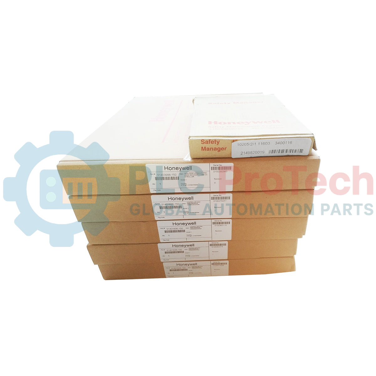
Honeywell

Honeywell 10205/2/1 11600 FSC 2-Channel Fail-Safe Analog Output Module

SKU 10205/2/1

In stock
  • 12-month warranty
  • Free returns within 30 days
  • Manufacturer: Honeywell

  • Product No.: 10205/2/1

  • Country of origin:United States

  • Product Type: Fail-Safe Analog Output Module

  • Payment: T/T, Western Union

  • Weight: 500g

  • Dimensions: Approx. 175 × 125 × 25 mm (historical, unverified); 4 HP × 3U rack

  • Shipping port: Xiamen

  • Warranty: 12 months

Honeywell 10205/2/1 (ordering code 11600) is a two-channel fail-safe analog output module for the Honeywell Fail Safe Control (FSC) platform. Each channel delivers a configurable 0–20 mA or 4–20 mA current signal in an active (internally powered) or passive (externally powered) loop arrangement. It is intended for non-redundant FSC I/O configurations; the output currents cannot be paralleled for redundant operation.

Technical Specifications

Manufacturer Honeywell Safety Management Systems
Product / order code 10205/2/1 / 11600
Platform Honeywell FSC (Fail Safe Control)
Module function Fail-safe analog current output
Number of outputs 2
Output ranges 0–20 mA or 4–20 mA; active or passive loop modes
D/A conversion 12-bit per output; A/D output-value monitoring for diagnostics
5 VDC supply requirement 30 mA
24 VDC supply requirement 65 mA base load, plus 30 mA for each active output
Off-state current Less than 0.05 mA
Active output: maximum loop resistance 1 kΩ
Active output: maximum output voltage 30 VDC
Passive output: external supply 40 VDC maximum; minimum module voltage drop 7.5 V
Watchdog input current 0.5 mA
Isolation Analog outputs isolated from 5 VDC and 24 VDC supplies; output 0 V terminals internally commoned
Rack space 4 HP (4 TE), 3U (3 HE)
Module / rack key coding A9 and C5
Historical software requirement FSC software version 3.00 as listed in the Hardware Manual; verify installed system release
I/O redundancy Non-redundant I/O configurations only

Output Modes and Termination

When used with FSC I/O backplanes, each output requires a corresponding 10205/A/. analog output mode module at the backplane programming connector. The 10205/A/1 configures internally powered current-source operation for a passive field load; 10205/A/2 configures externally powered current regulation for an active field device. The 10205/A/3 dummy mode module is used to terminate an unused output channel. Verify which mode card is installed on each channel before replacing the output module.

The historical FSC manual permits resistive or capacitive loads; inductive loads may trigger module fault reporting. The 24 VDC feed remains necessary even when a loop is configured for external power. On an unused channel, the required dummy or specified shorting arrangement prevents the module's self-test from raising a fault.

Diagnostics and Commissioning

Each channel includes D/A conversion and an A/D readback path. The FSC system can check output-value agreement, ability to de-energize, and cross-channel effects within the configured process safety time. This diagnostic architecture does not establish that a particular installed application meets a safety integrity level by itself; the configured system and field circuit must be evaluated independently.

During replacement, document the original 10205/2/1 11600 order code, rack keying, backplane type, installed 10205/A mode cards, loop wiring, control-system release and process safety configuration. After controlled installation, verify the output ranges, loop current with an appropriate meter, unused-channel termination, watchdog response and fault indication under site-approved commissioning procedures. The module has P2/P3 calibration potentiometers; do not alter calibration without the FSC procedure and suitable test equipment.

Dimensions, Weight and Air-Freight Planning

The Honeywell hardware manual specifies 4 HP × 3U rack space, not a complete shipping-carton dimension. Historical spare-parts listings report an approximate module envelope of 175 × 125 × 25 mm, but these measurements and the listed net weights differ between suppliers; confirm the actual stocked unit before treating them as final dimensions or weight.

Estimated protective package: 240 × 180 × 90 mm. Estimated shipping weight: 0.8 kg. These are preliminary courier/freight-planning estimates, not Honeywell OEM package specifications. Final chargeable dimensions and gross weight must come from the warehouse after protective packing. The previous draft's 325 × 150 × 150 mm figure appears in third-party documentation for a separate associated termination/motherboard assembly and must not be presented as the physical dimensions of the 10205/2/1 module.

Ordering and Replacement Information

Module: 10205/2/1. Ordering code: 11600. Confirm the complete marking on the stocked unit and whether the required 10205/A/1, /A/2 or /A/3 mode cards, termination assembly and cables are supplied separately. Do not assume 10205/1/1 is an unconditional plug-in replacement: its rack keying and system implementation differ. Availability and exact package measurements should be reconfirmed before shipment.

FAQ

What is the output range of Honeywell 10205/2/1?

The FSC 10205/2/1 has two analog current outputs. Each supports 0–20 mA or 4–20 mA and can be configured for internally powered (active) or externally powered (passive) operation using the corresponding 10205/A mode module.

Can 10205/2/1 be used in a redundant FSC I/O configuration?

No. The historical Honeywell FSC Hardware Manual specifies non-redundant I/O configurations only, because these analog current outputs cannot be paralleled for redundant operation.

What power supplies are required?

The module draws 30 mA from 5 VDC and 65 mA from 24 VDC, plus 30 mA for each output configured as active. The 24 VDC supply is required even with an externally powered output loop.

What do 10205/A/1, 10205/A/2, and 10205/A/3 do?

10205/A/1 configures internally powered current-source operation, 10205/A/2 configures externally powered current regulation, and 10205/A/3 is a dummy mode card for an unused output channel. Confirm the backplane and installed mode card before replacement.

Are 325 × 150 × 150 mm and 7 kg the module's confirmed dimensions and weight?

No. The 325 × 150 × 150 mm dimensions appear in a separate termination/motherboard assembly listing and must not be treated as the 10205/2/1 module envelope. The product page labels its 240 × 180 × 90 mm carton and 0.8 kg shipping weight as estimates only; the final shipped unit requires warehouse measurement.

Can 10205/1/1 directly replace 10205/2/1?

Do not assume direct interchangeability. They share broadly similar analog output functions but differ in rack key coding and documented configuration details. Check full order code, backplane, system release, mode cards and approved migration procedure.

View all FAQs →

Quantity
Shipping & Returns

Global Express Shipping

  • Standard Delivery: 4–6 business days via DHL, FedEx, and UPS.
  • Express Dispatch: Same-day dispatch for in-stock orders placed before 2:00 PM (GMT+8).
  • Worldwide Coverage: Serving over 150 countries.

Returns & Warranty

  • 30-Day Guarantee: Returns accepted for in-stock products in original, factory-sealed packaging.
  • 12-Month Warranty: Every industrial component is backed by our technical warranty.
Reviews
1 of 1
Only 6 item(s) left in stock
Quantity
View full details
Loading product navigation…

Global Express Shipping

  • Standard Delivery: 4-6 Business Days via DHL, FedEx, and UPS.
  • Express Dispatch: Same-day dispatch for in-stock orders placed before 2:00 PM (GMT+8).
  • Worldwide Coverage: Serving over 150 countries, including rapid delivery to Saudi Arabia and UAE.

Returns & Warranty

  • 30-Day Guarantee: Returns accepted for in-stock products in original, factory-sealed packaging.
  • 12-Month Warranty: Every industrial component is backed by our professional technical warranty.

Orders are processed and delivered Monday-Friday (excluding public holidays).


For full eligibility, restocking fees, and international return details, please view our official Refund & Return Policy .

TECHNICAL SPECIFICATIONS

Country of origin
United States

Technical knowledge

1746-A7 Chassis Replacement Checks: Slots, Power and Interconnects

An engineering checklist for replacing an Allen-Bradley 1746-A7: verify chassis series, backplane loading, slot plan, interconnect cables, mounting, grounding and receiving condition.

IC200MDL650 Replacement Checks: Logic Polarity, Filters, and Commons

A field replacement guide for GE Fanuc IC200MDL650 covering revision-dependent negative logic, four common groups, 24 VDC thresholds, input filtering, carrier checks and commissioning records.

IC697CPX935 Replacement Checks: Memory, Ports, and Rack Power

A field-focused IC697CPX935 replacement guide covering fast memory, firmware-dependent serial behavior, rack power, cooling, I/O architecture and backup records.

IC693DSM324 Replacement Checks: FSSB, Firmware and Follower Control

A field-focused IC693DSM324 replacement guide covering Series 90-30 host checks, FSSB servo-chain records, 5 V power budget, firmware limits, follower control and commissioning.

HIMA F3430 Replacement Checks: Contact Ratings and Safety Limits

A field-focused HIMA F3430 replacement guide covering relay contact ratings, DC load derating, fusing, F3330/F3331 differences, safety restrictions and commissioning records.

IC697PWR710 Replacement Checks: Load Budget and Dual-Rack Limits

A field-focused IC697PWR710 replacement guide covering 5 V load calculations, dual-rack limits, extension cables, input checks, protection behavior and hardware revision risks.