Description
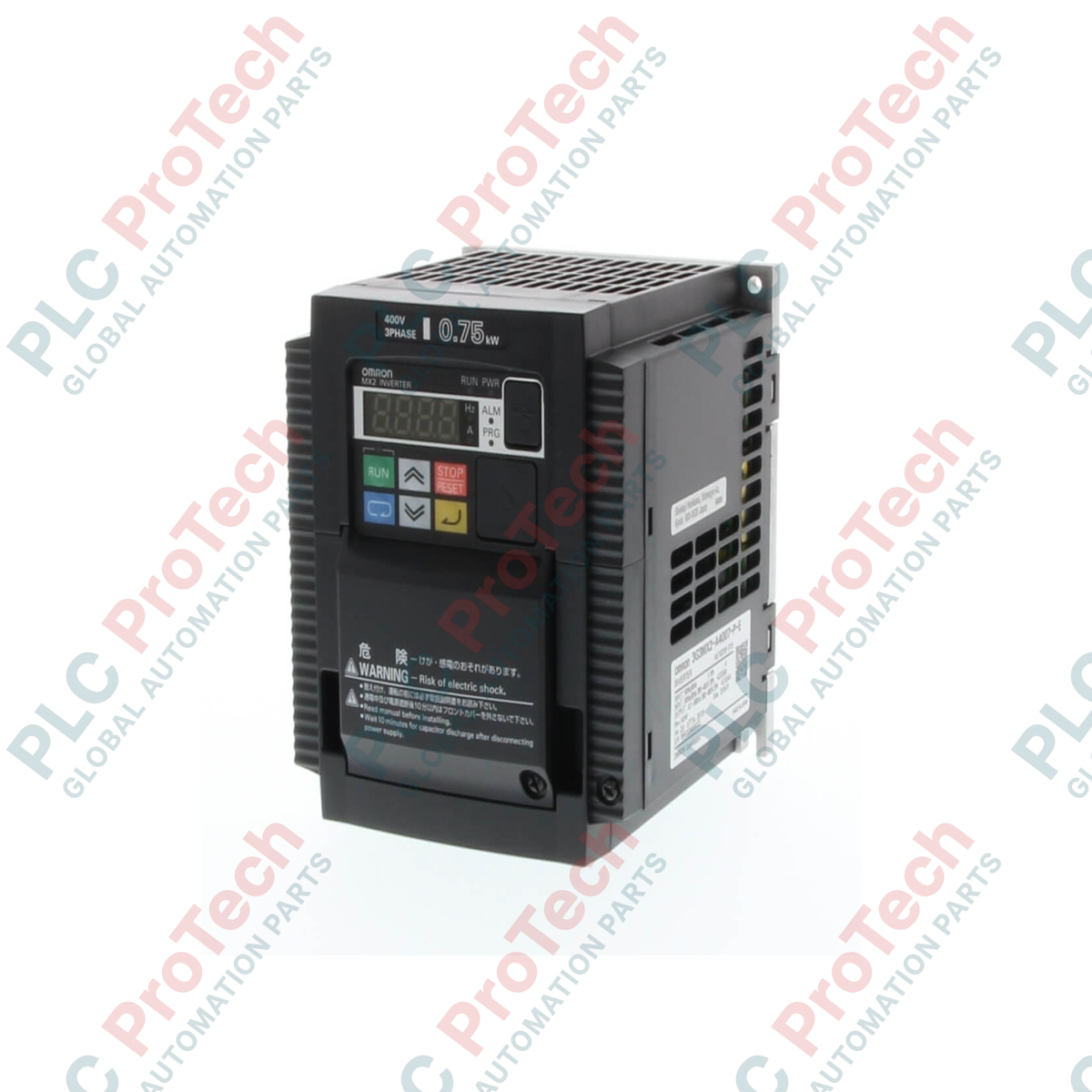
The Omron 3GEMX2-A4007-ZV1 is a high-performance multi-function compact inverter belonging to the MX2 Series (ZV1 full-featured version). Specifically engineered for high-precision machinery control, this drive coordinates advanced power and speed control at low speeds along with integrated functional safety.
Operating on a three-phase 400 V class power supply, the inverter is rated to drive a 0.75 kW three-phase AC induction or permanent magnet synchronous motor. Utilizing an advanced current vector control algorithm, it achieves a high starting torque of 200 percent at a low frequency of 0.5 Hz and delivers smooth four-quadrant operation under open-loop conditions. The drive features an integrated hardware-based Safe Torque Off (STO) function compliant with ISO 13849-1 (PLd, Cat.3), eliminating the need for external dual safety contactors to disconnect motor power, which minimizes enclosure footprint and control logic costs.
Features
- Dual rating design supports Heavy Duty (CT) and Light Duty (VT) operating modes via parameter configuration.
- High starting torque of 200 percent at 0.5 Hz achieved through sensorless current vector control.
- Built-in dual-channel safety inputs compliant with ISO 13849-1 Cat.3 PLd for Safe Torque Off (STO).
- Integrated simple positioning and pulse train input functionality for synchronized speed and position control without external controllers.
- Built-in Drive Programming capability supporting up to 140 lines of ladder logic for independent decentralized tasks.
- Standard RS-485 serial communication port with integrated Modbus-RTU protocol and support for optional industrial network cards.
- Advanced motor compatibility supporting both standard three-phase induction motors and Permanent Magnet Synchronous Motors (PM motors).
Applications
- Industrial conveyor lines and logistics handling systems
- Industrial hoisting, lifting mechanisms, and material handling cranes
- Centrifugal ventilation fans, multi-stage industrial pumps, and air compressors
- Winding machines, textile machinery, and slitter-rewinder tension controls
- Packaging machinery and food processing production line main drives
Technical Specifications
Model Configuration (3GEMX2-A4007-ZV1)
According to the Omron inverter nomenclature structure, the specific configuration parameters are decoded as follows:
| Option Position |
Configuration Item |
Technical Specification |
| Model |
Base Series Identifier |
3GEMX2 / 3G3MX2 High-performance Compact Series |
| Enclosure |
Enclosure Protection Class |
A = Panel-mounting type (IP20 minimum) |
| Voltage |
Input Supply Voltage Class |
4 = Three-phase 400 V AC Class (380 to 480 V) |
| Capacity |
Maximum Applicable Motor Capacity |
007 = 0.75 kW (1 HP) under Heavy Duty mode |
| Version |
Software/Function Edition |
ZV1 = Standard version with advanced functional programming |
Electrical
| Parameter |
Specification |
| Rated Input Voltage |
Three-phase 380 to 480 V AC, 50/60 Hz (Allowable fluctuation -15 percent to +10 percent) |
| Input Phase |
3-phase |
| Applicable Motor Capacity |
Heavy Duty (CT): 0.75 kW / Light Duty (VT): 1.1 kW |
| Rated Output Current |
Heavy Duty (CT): 2.5 A / Light Duty (VT): 3.4 A |
| Maximum Output Voltage |
Three-phase, 3-wire output from 0 V up to the input supply voltage level |
| Maximum Output Frequency |
0.1 to 400 Hz |
| Carrier Frequency |
2.0 to 15.0 kHz (Heavy Duty default rating typical at 3.0 kHz) |
Control Performance
| Parameter |
Specification |
| Control Method |
Sinusoidal PWM (V/f control, Sensorless Vector Control) |
| Starting Torque |
200 percent at 0.5 Hz when utilizing Sensorless Vector Control |
| Accel/Decel Time |
0.01 to 3,600.00 seconds (Supports linear and S-curve patterns) |
| Frequency Setting Resolution |
Digital Command: 0.01 Hz / Analog Command: 1/1,000 of maximum frequency |
Environmental Limits
| Parameter |
Specification |
| Operating Ambient Temperature |
-10 deg C to +50 deg C (Derating required if ambient exceeds nominal ratings) |
| Operating Ambient Humidity |
20 percent to 90 percent RH (Non-condensing, non-freezing) |
| Storage Temperature |
-20 deg C to +65 deg C (Short-term transportation conditions) |
| Installation Altitude |
1,000 meters maximum (Derate nominal capacity by 1 percent per 100 meters up to 3,000 meters) |
| Enclosure Rating |
IP20 |
Mechanical
| Parameter |
Specification |
| Net Weight |
1.6 kg |
| Cooling Method |
Forced air cooling via integrated internal fan |
Connections / Interfaces
Transmitter Control and Power Terminals
| Terminal Group |
Terminal Name |
Function |
| Main Power Circuits |
R, S, T |
Three-phase AC incoming line power supply terminals |
| Main Power Circuits |
U, V, W |
Three-phase AC variable frequency output terminals to motor |
| Main Power Circuits |
PD, P |
Connection terminals for an optional DC link choke (DCL) (Jumpered by default) |
| Main Power Circuits |
P, RB |
Connection terminals for an external dynamic braking resistor |
| Main Power Circuits |
G |
Protective Earth (PE) ground terminal |
| Control Inputs |
1, 2, 3, 4, 5, 6, 7 |
Multi-function digital logic inputs (Configurable for multi-step speed, reset, FW/REV, etc.) |
| Control Inputs |
P24 |
+24 Vdc control power supply common output (100 mA maximum current) |
| Control Inputs |
PLC |
Common terminal for digital inputs / external source power input (Sink/Source selectable) |
| Control Inputs |
H, O, OI, L |
Analog inputs (H: +10 Vdc ref, O: 0-10 Vdc voltage input, OI: 4-20 mA current input, L: Analog common) |
| Control Outputs |
11, 12 |
Multi-function open-collector digital outputs |
| Control Outputs |
CM2 |
Open-collector output common reference terminal |
| Control Outputs |
AM |
Analog voltage monitor output terminal (0 to 10 Vdc) |
| Control Outputs |
MA, MB, MC |
Multi-function internal relay output (MA: Normally Open, MB: Normally Closed, MC: Relay common) |
| Safety Interfaces |
GS1, GS2 |
Dual-channel independent safety inputs linked directly to internal output shutoff mechanism |
Installation Guidelines
- Cable Routing and Separation: Main power lines (Input supply lines R/S/T and motor output lines U/V/W) must be routed strictly apart from low-voltage control or communication wiring, maintaining a minimum parallel clearance of 10 cm to eliminate electromagnetic coupling.
- Shielding and Grounding: Connect the motor via a continuous three-phase shielded cable. The shield layer must achieve a 360-degree perimeter connection directly to the metal panel or grounding clamp on the drive side. The drive PE ground terminal must be connected to the plant main protective earth.
- Enclosure Ventilation Clearances: The inverter must be installed vertically on a flat, non-flammable surface inside the electrical panel. To maintain unhindered air convection, clear spaces of at least 100 mm must be maintained above and below the drive housing, and 50 mm must be maintained on the left and right sides.
- EMI/RFI Mitigation: For noise-sensitive plant environments, install a dedicated three-phase AC radio noise filter on the line input side of the drive and wind the motor output phases through a ferrite core to suppress conducted and radiated emissions.
- Safety Shorting Jumpers: The drive is delivered with factory-installed shorting links between the safety input terminals (GS1, GS2) and the common logic level. When implementing a hardware safety relay circuit, these jumpers must be removed to wire the emergency stop line correctly.
Compliance and Certifications
- CE: Certified under Low Voltage Directive 2014/35/EU and EMC Directive 2014/30/EU.
- UL/cUL: Listed under industrial control equipment standards UL 508C and CSA C22.2 No.14.
- Functional Safety: Certified to ISO 13849-1:2006 Category 3 PLd and IEC 61508 SIL2.
- RoHS: Compliant with standard restrictions on hazardous substances.
FAQ
Q1: What is the main configuration distinction between Heavy Duty (CT) and Light Duty (VT) modes for the 3GEMX2-A4007-ZV1?
A1: Under Heavy Duty (CT) mode, the inverter handles up to a 0.75 kW motor with 150 percent overload capacity for 60 seconds. Under Light Duty (VT) mode, the rated output current increases to handle a 1.1 kW motor but the overload capacity drops to 120 percent for 60 seconds, which is suitable for variable-torque fans or pumps.
Q2: Can this inverter drive a permanent magnet motor, or is it restricted to standard induction motors?
A2: The ZV1 series firmware integrates permanent magnet synchronous motor (PM motor) control capabilities alongside standard three-phase AC induction motor algorithms, permitting open-loop speed and torque control for synchronous energy-saving motors.
Q3: How do I switch the digital input logic between SINK and SOURCE wiring?
A3: The logic selection is changed by moving the slide switch located near the control terminal block or by modifying the wiring connection at the PLC common terminal block according to the desired external PNP or NPN logic interface.
Q4: What happens if the internal cooling fan encounters a mechanical block or fault?
A4: The drive detects cooling abnormalities and generates an internal fault code, triggering an automatic trip sequence to prevent thermal runaway of the power IGBT modules.
Q5: Can the 3GEMX2-A4007-ZV1 operate as a standalone logic controller?
A5: Yes. Through the built-in Drive Programming function, technicians can compile and execute up to 140 lines of ladder logic diagrams directly within the inverter CPU to process local I/O tasks without an external PLC.
Q6: What is the minimum carrier frequency setting, and how does it affect heat dissipation?
A6: The carrier frequency can be adjusted between 2.0 kHz and 15.0 kHz. Lowering the carrier frequency decreases the thermal loss inside the inverter modules but increases audible acoustic motor hum.
Q7: What is the purpose of the built-in Modbus-RTU communication interface?
A7: The built-in RS-485 port allows up to 32 drives to be networked under a single master controller to parameterize, control, and read back status variables using standard Modbus frame structures.
Q8: Does this compact drive require external dynamic braking transistors?
A8: No. The A4007 drive includes an integrated internal braking chopper transistor. Dynamic braking resistors can be wired directly across terminals P and RB without requiring a separate external braking unit.
Q9: What is the operational response of the built-in functional safety system?
A9: De-energizing either the GS1 or GS2 terminal causes the internal gate-drive circuit to safely isolate power from the output IGBTs within milliseconds. This achieves an uncontrolled stop equivalent to emergency stop Category 0 per IEC 60204-1.
Q10: How does an elevated installation altitude affect the drive rating?
A10: At elevations above 1,000 meters, the thinner air reduces convective cooling efficiency. The continuous output current of the drive must be derated by 1 percent for every additional 100 meters of elevation up to 3,000 meters.
Q11: Can this inverter accept a single-phase 230 V supply to output 400 V three-phase power?
A11: No, the 3GEMX2-A4007-ZV1 is designed strictly for three-phase 380 to 480 V AC inputs. Utilizing single-phase input or improper voltage thresholds will trigger an immediate input phase loss or undervoltage fault protection trip.
Q12: How can I reset an active overcurrent or overvoltage error on the inverter?
A12: Errors can be reset by applying a digital logic high signal to a digital input terminal configured for the Reset function, executing a reset command via Modbus communication, or cycling the main input power supply.
Q13: What terminal should be used for a 4 to 20 mA analog speed reference command?
A13: The 4 to 20 mA loop input must be wired directly to the OI terminal, with the loop common connected to the L terminal. The input selection parameter must be configured to prioritize the OI analog interface.