


Derivative Action in PID Control Without Noise Problems
Learn what derivative action contributes to a PID loop, why it can amplify measurement noise and setpoint changes, and how filtering, sampling, and staged tests make D tuning safer.
Manufacturer: ABB
Product No.: IMDSO14
Country of origin:Switzerland
Product Type: Digital Output Module
Barcode: 8537101190
Payment: T/T, Western Union
Weight: 500g
Dimensions: 3.5 cm x 17.8 cm x 29.8 cm (W x H x D)
Shipping port: Xiamen
Warranty: 12 months
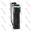
The ABB Bailey IMDSO14 Digital Output Module functions as an interface between the INFI 90 OPEN Strategic Process Management System and process field devices. It receives commands from control modules—such as the multi-function processor (MFP), multi-function controller (MFC), or logic master module (LMM)—over the I/O expander bus to switch field equipment ON or OFF. The IMDSO14 provides 16 digital outputs through solid-state circuitry, where 12 outputs are individually isolated and two pairs share positive output terminals. It handles 24 VDC or 48 VDC load voltages and serves as a direct replacement for the IMDSO04 module.
| Property | Value |
|---|---|
| Manufacturer | ABB / Elsag Bailey |
| Power Requirements (Voltage) | 5 VDC (+/-5%) |
| Power Requirements (Current) | 275 mA (typical), 370 mA (maximum) |
| Power Dissipation (Logic Only) | 1.375 W (typical), 1.850 W (maximum) |
| Number of Outputs | 16 digital |
| Load Voltage | 24 VDC, 48 VDC |
| Load Current (Maximum) | 250 mA (24 VDC), 125 mA (48 VDC) |
| Off Leakage Current (Maximum) | 10 uA at 70 degC (158 degF) |
| On Voltage Drop (Maximum) | 2 V at 70 degC (158 degF) |
| Current Consumption per Output | 150 mA typical / 250 mA max (24 VDC), 75 mA typical / 125 mA max (48 VDC) |
| Isolation (Channel-to-Channel & Channel-to-Logic) | 100 Mohm insulation resistance, 1 kV rms / 1 min or 1.5 kVDC / 1 min |
| Mounting | Occupies one slot in a standard INFI 90 OPEN module mounting unit |
| Operating Temperature (Cabinet Internal) | 0 to 70 degC (32 to 158 degF) |
| Relative Humidity | 5% to 95% up to 55 degC (131 degF) noncondensing, 5% to 45% at 70 degC (158 degF) noncondensing |
| Atmospheric Pressure | Sea level to 3 km (1.86 miles) |
| Air Quality | ISA S71.04, Class LA, LB, LC-level 1 (Noncorrosive) |
| Connector Pin | Function |
|---|---|
| P1 Pins 1, 2 | +5 VDC Logic Power |
| P1 Pins 5, 6 | Common |
| P1 Pins 9, 10 | Power Fail Interrupt (PFI) |
| P1 Pins 3, 4, 7, 8, 11, 12 | NC (Not Connected) |
| P2 Pins 1 to 8 | I/O Expander Bus Data Lines (Data 0 to Data 7) |
| P2 Pin 9 | I/O Expander Bus Clock |
| P2 Pin 10 | I/O Expander Bus Sync |
| P2 Pins 11, 12 | NC (Not Connected) |
| P3 Group A Pins A/1 to H/J | Digital Output Signals 1 to 8 (Group A) |
| P3 Group B Pins K/9 to S/8 | Digital Output Signals 9 to 16 (Group B) |


Global Express Shipping
Returns & Warranty


| Product Image | Model Number / Title | Condition | Availability | Action |
|---|---|---|---|---|

|
Allen-Bradley 1746-OVP16 SLC 500 Digital DC Output Module | Original New | In Stock | View Details |
|
Allen-Bradley 1756-OB8 ControlLogix DC Digital Output Module | Original New | In Stock | View Details |

|
Allen-Bradley 1794-OB16P FLEX I/O Digital DC Output Module | Original New | In Stock | View Details |
Global Express Shipping
Returns & Warranty
Orders are processed and delivered Monday-Friday (excluding public holidays).
For full eligibility, restocking fees, and international return details, please view our official Refund & Return Policy .
| Color pattern |
Green
|
| Country of origin |
Switzerland
|
| Power source |
DC Power
|

Learn what derivative action contributes to a PID loop, why it can amplify measurement noise and setpoint changes, and how filtering, sampling, and staged tests make D tuning safer.

A practical guide to segmenting, documenting, and testing industrial Ethernet networks so plant teams can isolate faults quickly, control change, and expand without creating fragile dependencies.

Commission IO-Link systematically from master addressing and port modes through IODD selection, PLC byte mapping, parameter backups, device validation, and failure-injection tests.

A practical PowerFlex braking guide covering regenerative energy, resistor resistance and duty cycle, thermal protection, model-specific parameters, and measured commissioning tests.

An industrial joystick is only the first element in a safe motion command chain. This guide covers sensing choices, wiring, signal validation, PLC logic, restart behavior, and commissioning for...

PID tuning becomes safer when engineers can see how proportional, integral, and derivative actions reshape error, output, and response over time. This guide turns live trends into a disciplined...