Summary
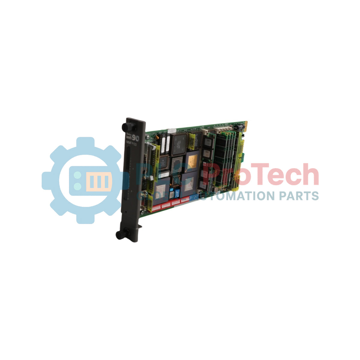
The IMMFP03 (IMMFP03) stands as a high-capacity, standalone multi-function processor module designed for the ABB Bailey INFI 90 and Harmony Rack distributed control systems. Engineered for data-intensive, program-heavy applications across continuous industrial sectors including baseload power generation, chemical refining complexes, and large-scale metallurgical operations, this 32-bit computing engine simultaneously orchestrates advanced analog, sequential, and batch control configurations. Operating on a 32 MHz platform with direct memory access (DMA) processing, the IMMFP03 manages communications for up to 64 decentralized I/O modules via its high-speed expander bus. Implementing this module within your core DCS architecture ensures deterministic execution of loop optimization and performance modeling routines while providing seamless, bumpless hot-standby redundancy that keeps critical plant processes online during unexpected physical processor interruptions.
System Architecture and Communication Protocols
The underlying engineering design of the IMMFP03 card provides comprehensive subsystem coordination, high-density memory paths, and native serial interfacing through optional expansion hardware.
-
Onboard Memory Framework: Features 2 megabytes of high-speed Static Random Access Memory (SRAM) tied to a native 32-bit wide data path across all memory segments (including NVRAM and ROM), ensuring zero-wait-state processing for complex function block structures.
-
Hot-Standby Redundancy Path: Integrates an onboard high-speed parallel redundancy link capable of handling up to 8 Mbytes maximum throughput (4 Mbytes under normal operation) for real-time tracking between primary and secondary processors.
-
Expander Bus Optimization: Employs an automated Auto/DMA operation mode on the I/O Expander Bus to handle multi-channel inputs and outputs without imposing cycle-time latency on the central microprocessor.
-
Auxiliary Station Interfacing: Combines with the optional IMMPI01 Interface Module to establish dedicated direct memory access (DMA) driven links supporting up to 64 40-kbaud serial Analog Control Stations (IISAC01) or up to 8 5-kbaud serial Digital Control Stations (NDCS03), alongside dual RS-232-C / RS-485 serial communication networks.
Comprehensive Hardware Specifications
| Engineering Metric |
Detailed Characteristic Values |
| Model Designation |
IMMFP03 |
| Brand Identity |
ABB Bailey |
| System Compatibility |
INFI 90 / Harmony Rack Systems |
| Microprocessor Core |
32-bit processing unit running at 32 MHz |
| Onboard SRAM Capacity |
2 Megabytes (32-bit data path width) |
| Country of Origin |
United States (US) |
| Net Hardware Weight |
0.84 kg |
| Physical Width |
35.56 mm (1.40 in) |
| Physical Height |
177.80 mm (7.00 in) |
| Physical Length |
298.45 mm (11.75 in) |
| Power Consumption |
+5 VDC at 2 A nominal (10 W typical dissipation) |
| Programmable Languages |
C, Basic, Batch, Ladder Logic, standard Function Blocks |
| Atmospheric Limit |
Sea level up to 3 km (1.86 mi) operating elevation |
| Environmental Temperature |
0 to 70 deg C (32 to 158 deg F) operational range |
| Relative Humidity Span |
0% to 95% up to 55 deg C, derating to 45% max at 70 deg C (Non-condensing) |
| Agency Certification |
CSA certified for process control equipment in ordinary locations |
Technical Troubleshooting FAQs
How does the Machine Fault Timer (MFT) safeguard the process if the IMMFP03 hangs?
The Machine Fault Timer is a hardware watchdog circuit that must be continuously reset by the 32-bit processor during normal loop execution. If an internal firmware exception or memory parity error halts the program execution, the MFT times out, immediately shutting down the module outputs and initiating an automatic bumpless transfer of control to the standby backup processor card.
What is the functional difference between the IMMFP03 and the IMMFP03B variants?
The main difference lies within the onboard Static RAM configuration. The standard IMMFP03 features 2 megabytes of SRAM, while the high-density IMMFP03B variant expands this memory layer to 8 megabytes. Both models utilize identical form factors, backplane pinouts, and 32 MHz processor cores, allowing them to use the same termination units and cabinet footprints.
How do engineers interpret the 16 CPU LEDs visible through the front faceplate window?
The 16 red CPU LEDs display real-time error codes, system status matrices, and initialization progress indicators. During normal operation, these LEDs flash pattern sequences indicating background cycle execution. A steady, frozen LED pattern combined with a red Status LED indicates a specific hardware failure or configuration error code, which can be cross-referenced with the system diagnosis manual.
On-Site Commissioning and Field Engineering Directives
-
Electrostatic Discharge Mitigation and Storage: The IMMFP03 contains high-density CMOS components vulnerable to electrostatic voltage spikes. Keep the processor card in its anti-static shielding bag until installation. Technicians must wear a properly bonded ESD wrist strap connected to the metal cabinet frame prior to touching the circuit board or adjusting onboard dipswitches.
-
Chassis Positioning and Thermal Airflow Rules: The module assembly requires one physical slot within an INFI 90 Module Mounting Unit (MMU). Note that an adjacent slot immediately to the left of the MFP module must be left open or reserved for the optional IMMPI01 auxiliary I/O interface module. Ensure the top and bottom captive faceplate thumbscrews are firmly locked into the MMU frame to complete the chassis ground plane and maintain proper un-obstructed vertical convective cooling airflow through the cabinet slots.
-
Cabinet Radio Frequency Isolation (RFI): Onboard processing lines can be affected by close-range radio frequency interference. Field personnel must maintain cabinet door integrity during active plant operations. Avoid utilizing portable handheld radio transceivers or digital communication hardware closer than 2 meters from an un-shielded or open processor enclosure.
-
On-Line Configuration and NVRAM Preservation: When executing online tuning or modifying function codes through the engineering workstation, verify the internal backup battery status. The onboard non-volatile random-access memory (NVRAM) preserves modified tuning constants and step variables during power outages. Check battery shelf-life metrics during routine annual maintenance shutdowns to ensure data retention integrity.