Hardware Overview
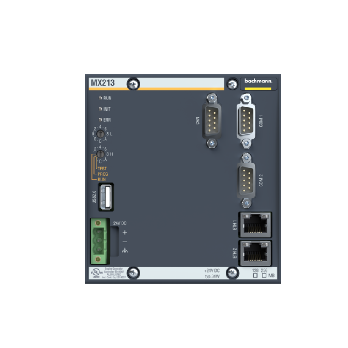
The MX213 (MX213/512 CF) processor module functions as the high-performance central processing unit for the Bachmann M1 automation platform, engineered specifically for high-demand industrial sectors like wind energy turbine control, maritime propulsion, and large-scale power generation infrastructure. This control unit interfaces directly with modular backplane networks to deliver deterministic program execution under rigorous field conditions. By consolidating a 266 MHz low-voltage industrial x86 processor with comprehensive communication options and an integrated 17 W power supply, the unit coordinates real-time data acquisition and complex logic control. Its solid-state hardware framework minimizes moving parts, which dramatically improves mean time between failures (MTBF) and eliminates unplanned plant downtime in continuous-process operations.
Comprehensive Technical Configuration
The architectural integrity of this processor core relies on an optimized x86/AMD LX execution model that delivers sub-millisecond task cycle times. Data retention relies on a split-memory structure: 256 MB of volatile DRAM manages active runtime processes, while a 512 kB NVRAM system permanently captures critical retain variables and system states without requiring battery backup.
For horizontal and vertical network integration, the hardware features multiple dedicated onboard communication interfaces:
-
Dual 100 Base-TX Ethernet Ports: Provides separate IP channels for deterministic machine-to-machine interlocking and SCADA data transmission.
-
Onboard CAN/CANopen Channel: Facilitates native fieldbus master/slave integration for remote I/O sub-assemblies.
-
Dual RS232/422/485 Serial Interfaces: Supports point-to-point industrial telemetry and legacy device connections.
Storage expansion uses a heavy-duty CompactFlash slot that supports industrial CF cards up to 2 GB for extensive event logging, system recipes, and local application backups.
Core Parameter Specifications
| Technical Parameter |
Engineering Value |
| Model |
MX213 (Spare Model: MX 213/512 CF) |
| Brand |
Bachmann Electronic |
| Origin |
Austria |
| Weight |
0.7 kg |
| Dimensions |
11.0 x 6.0 x 11.8 cm |
| Operating Temperature |
-30 to 60 deg C |
| Power Consumption |
33.6 W (Maximum with fully loaded I/O modules) |
| Processor Type |
AMD LX x86, 266 MHz |
| System Memory |
256 MB DRAM / 16 MB File-Flash |
| Retentive Memory |
512 kB NVRAM |
| Input Supply Voltage |
24 VDC (Acceptable tolerance band: 18 to 34 V) |
| Integrated Power Supply |
17 W output capacity |
| Tariff Code |
8537101190 |
Product FAQs
How does the module manage critical variable storage during an abrupt 24 VDC power disruption?
The unit features an onboard hardware monitoring circuit that detects supply voltage drops below acceptable limits. Upon detection, the system uses the residual energy stored in the internal power supply capacitors to write all designated retain data directly into the 512 kB non-volatile NVRAM. This architecture ensures complete data preservation without the failure risks of traditional lithium batteries.
Can the dual Ethernet interfaces on this control unit be configured on independent subnets?
Yes. The two physical Ethernet ports (2x ETH100) are assigned separate MAC addresses and link layers. Engineers can configure them with distinct IP addresses on independent subnets to isolate deterministic machine network traffic from standard corporate plant networks.
What are the direct drop-in replacement procedures if updating an older MX200 processor variant?
The MX213 maintains complete downward compatibility with previous Bachmann M1 software deployments. When replacing an older variant, the application code compiled for the x86 architecture can be transferred via the CompactFlash card. However, you must verify that the target firmware version supports the integrated communication controllers on the newer hardware.
Engineering & Installation Guide
Thermal Management & Airflow Clearances
To maintain structural stability up to the maximum 60 deg C rating, you must install the controller chassis vertically on a standard DIN rail. Maintain a minimum clear boundary space of 80 mm above and below the module housing. This spatial clearance generates natural convective airflow, preventing localized heat pockets inside the enclosure and protecting the low-voltage internal silicon components from premature thermal breakdown.
Grounding and Shielding Protocols
All fieldbus communication links (specifically CANopen and RS485 lines) must use shielded twisted-pair cabling. Terminate the cable shields directly at the entry point of the electrical cabinet using low-impedance ground clamps. The DIN rail itself must connect to the central plant functional earth via a copper conductor with a minimum cross-section of 10 square millimeters to neutralize high-frequency electromagnetic noise.
Power Distribution Protection
The 24 VDC input supply line requires protection via a fast-acting circuit breaker or fuse rated at a maximum of 4.0 A. To prevent ground loops and common-mode voltage fluctuations from destabilizing the x86 processor core, do not share the primary 24 VDC automation power bus with inductive switching elements, such as heavy-duty motor contactors or hydraulic solenoids.