Product Summary
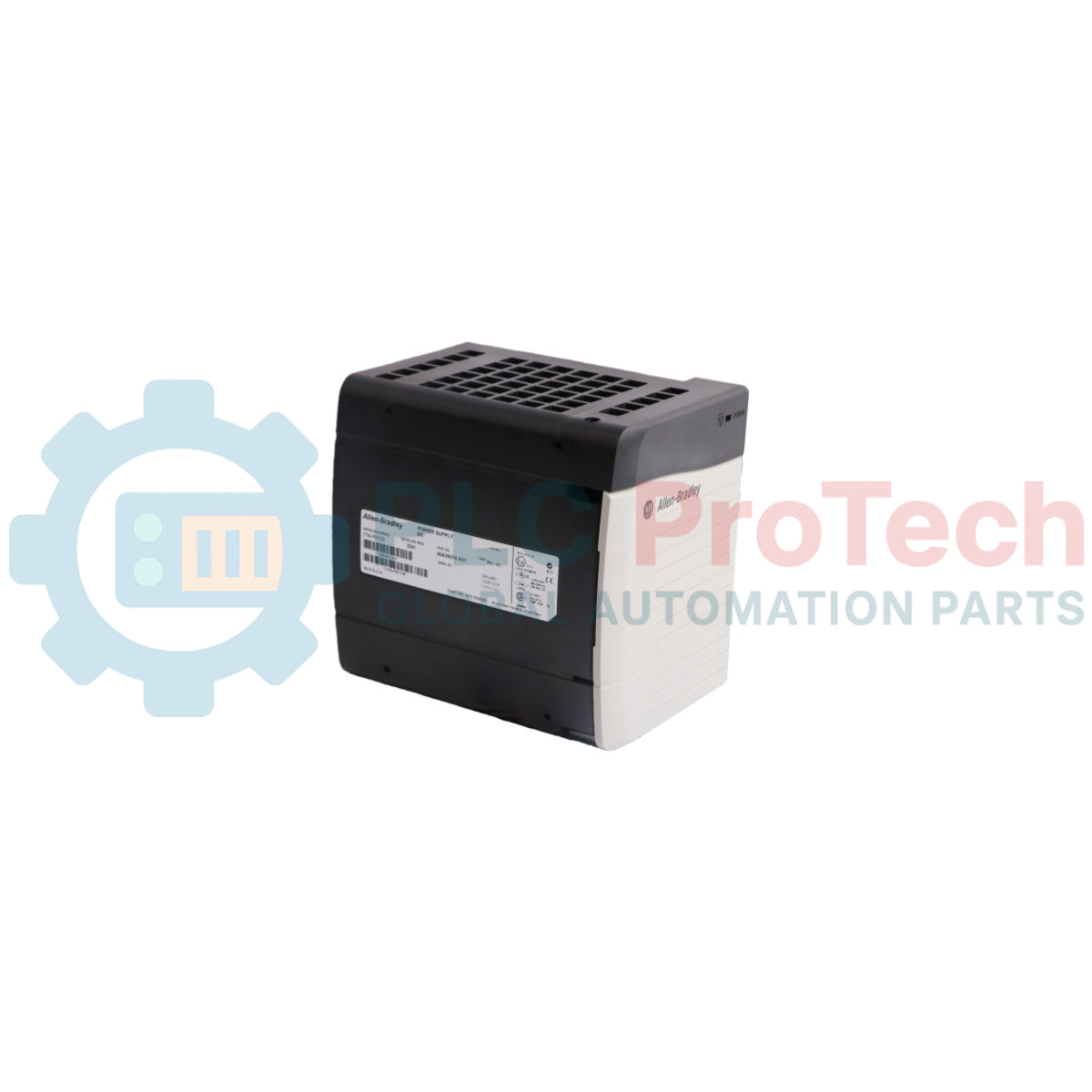
The 1756-PB75 is a heavy-duty chassis power supply within the Allen-Bradley ControlLogix platform, engineered to convert 24 VDC nominal source electricity into regulated backplane voltages. Designed for critical infrastructure deployment in oil and gas extraction, automated manufacturing, and heavy infrastructure substations, this module delivers stable current to local processing racks. By securing a high current capacity across all three operational backplane rails, it prevents voltage sags and module resets, directly reducing unplanned system downtime. The unit mounts directly to the left side of any standard 1756 ControlLogix chassis, integrating into the physical architecture without occupying standard I/O slots.
Technical Configuration
The hardware architecture of the 1756-PB75 utilizes advanced switch-mode power conversion to provide exceptional thermal and electrical efficiency across its entire load spectrum. It distributes a combined maximum power output of 75 W at 60 deg C, managing current allocation across the 1.2 V, 3.3 V, and 24 VDC backplane paths. Equipped with robust overcurrent, short-circuit, and overvoltage protection networks, the power supply automatically isolates internal faults to safeguard the multi-million dollar processor and communications architecture connected to the backplane. The input stage features an engineered line filter to suppress industrial electromagnetic interference (EMI) and ride through transient voltage drops. Status indication is handled via a prominent front-panel LED that gives real-time health readouts of the source input and internal conversion metrics.
Technical Specifications
| Parameter |
Technical Data |
| Model |
1756-PB75 |
| Brand |
Allen-Bradley |
| Series |
ControlLogix Chassis Power Supplies |
| Input Voltage Range |
18 to 32 VDC (24 VDC nominal) |
| Input Power (Max) |
95 W |
| Total Output Power (Max) |
75 W @ 60 deg C |
| Backplane Output Current (1.2 VDC) |
1.5 A |
| Backplane Output Current (3.3 VDC) |
4.0 A |
| Backplane Output Current (5.1 VDC) |
13.0 A |
| Backplane Output Current (24 VDC) |
2.8 A |
| Inrush Current (Max) |
30 A |
| Isolation Voltage |
250 V continuous (reinforced insulation type), input-to-backplane tested at 2500 VDC for 60 seconds |
| Overcurrent Protection |
Internal fuse (non-replaceable) and electronic current limiting |
| Conductor Strip Length |
8 mm (0.31 inches) |
| Recommended Wire Size |
2.5 mm sq (14 AWG) solid or stranded copper wire rated at 90 deg C minimum |
| Operating Temperature |
0 to 60 deg C (32 to 140 deg F) |
| Dimensions (H x W x D) |
140 x 112 x 145 mm (5.51 x 4.41 x 5.71 inches) |
| Weight |
0.95 kg (2.10 lbs) |
| Origin |
USA |
FAQs
What causes the front-panel LED on the 1756-PB75 to remain unlit or turn off completely?
An unlit LED indicates either a total loss of input source voltage (below 18 VDC), an open internal protection fuse due to a severe hardware fault, or an overcurrent condition on the backplane causing the power supply to enter a protective shutdown cycle. Disconnect the supply from the chassis to isolate backplane short circuits during troubleshooting.
Can the 1756-PB75 be wired in parallel with another power supply for redundancy?
No. The standard 1756-PB75 does not support parallel operation or load-sharing configurations on a standard chassis. For redundant power architectures, you must utilize the specific redundant power supplies (such as the 1756-PB75R) paired with a 1756-CPR2 redundancy cable and appropriate chassis adapter.
Is the internal fuse of the 1756-PB75 field-replaceable after an overvoltage event?
No. The internal input fuse is a factory-sealed component designed as a secondary safety measure. If the fuse blows, it signifies major internal component breakdown, and the entire power supply unit must be sent to an authorized depot for repair or replaced completely.
Field Installation and Commissioning Guidelines
-
Chassis Fastening and Grounding: Slide the 1756-PB75 onto the left side of the ControlLogix chassis until the guide pins engage fully. Tighten the mounting screws securely to the chassis frame. Ensure the chassis grounding lug is bonded to the main enclosure ground bus using a low-impedance copper strap to provide adequate shielding against high-frequency line noise.
-
Input Wiring Configuration: Connect the 24 VDC supply lines using 2.5 mm sq (14 AWG) copper conductors. Ensure the positive wire is secured to the "+", the negative wire to the "-", and the equipment ground wire to the designated ground terminal on the terminal strip. Keep input power cables separate from signal-level I/O wiring to mitigate inductive cross-talk.
-
Thermal Management Clearances: Maintain minimum clearances around the power supply as specified by the enclosure design documents (typically 51 mm or 2.0 inches at the top and bottom). Do not obstruct the ventilation slots on the top or bottom of the module housing, as inadequate airflow will cause thermal degradation and premature component fatigue.