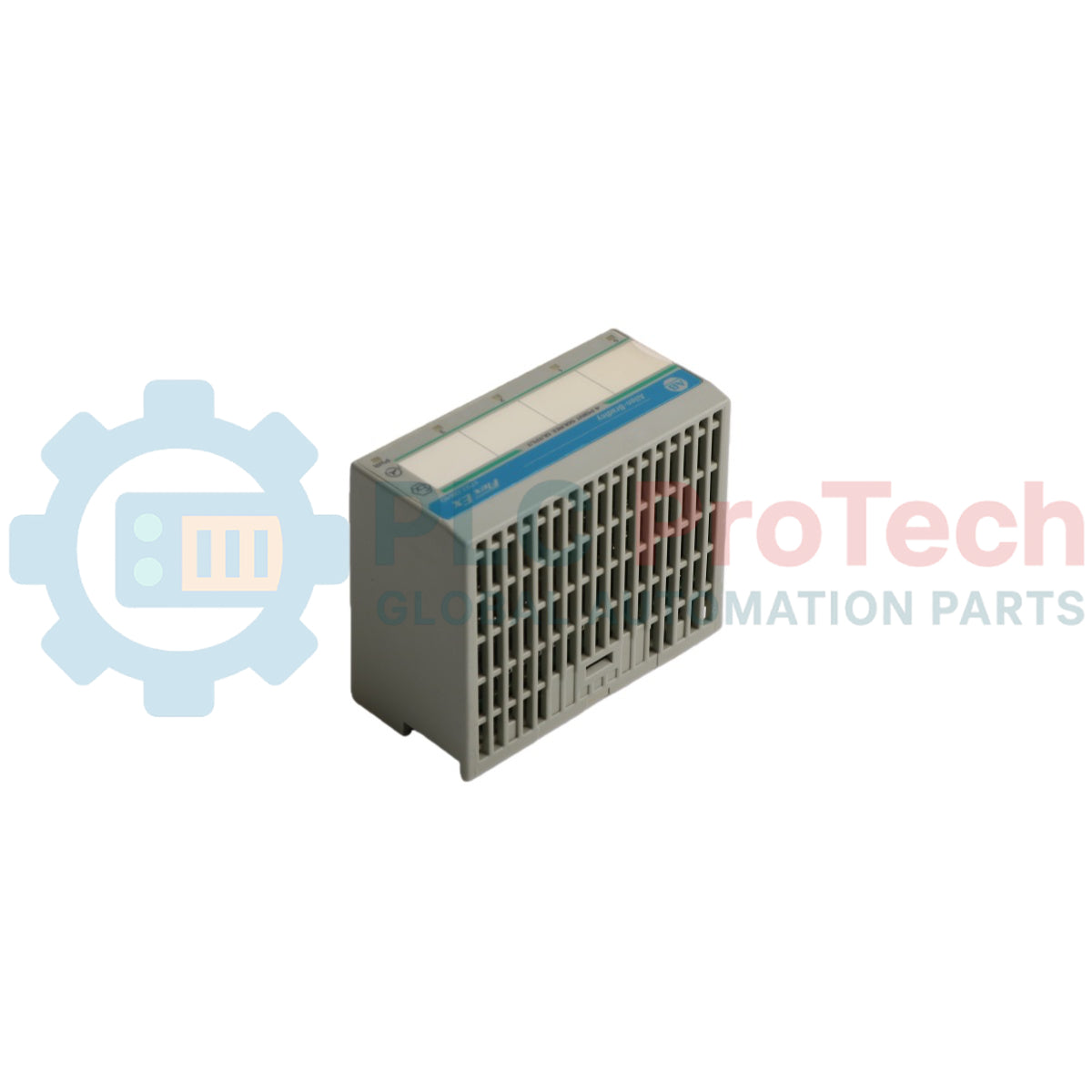
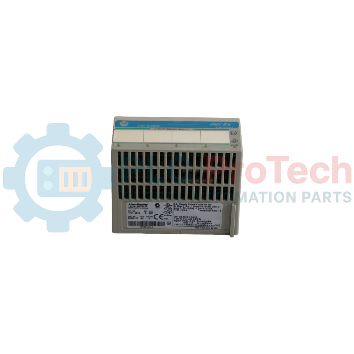
Allen-Bradley 1797-OB4D is a high-performance, intrinsically safe digital output module designed for hazardous area industrial environments. As part of the FLEX Ex I/O product family, this module provides 4 non-isolated, sourcing outputs specifically engineered to operate digital field devices such as valves, audible alarms, and solenoids.
The module features an integrated FlexBus communication interface which communicates seamlessly through compatible adapters like the ControlNet Ex adapter (1797-ACNR15) to achieve a robust, two-tier fault state mechanism across the backplane. This product is supplied as open-type equipment and must be installed on a 1797-TB3 or 1797-TB3S intrinsically safe terminal base unit inside a suitable enclosure , ensuring maximum system safety and environmental isolation.
The electrical architecture incorporates diagnostic indicators and sophisticated software configuration profiles accessible via RSLogix 5000. Every sourcing channel is electrically connected to one another and includes advanced electronic protection alongside selectable alarm filtering , making it an ideal choice for petro-chemical, chemical, gas, and automated process industries operating in Zone 1, Zone 2, or Zone 22 classifications.
Features
Built with 4 non-isolated, sourcing intrinsically safe digital outputs.
Designed for hot-swapping, allowing safe removal and insertion under power in nonhazardous conditions.
Comprehensive individual channel diagnostic capabilities including wire-off fault and overload detection.
Integrated software-configurable 100 Hz (10 ms) filter and adjustable alarm filter time constants (0.25 ms to 32 ms).
Selectable output fault behaviors allowing channels to either reset to zero or hold the last valid state.
Clear physical diagnostics featuring 4 yellow status indicators, 4 red fault indicators, and 1 green module power indicator.
Built-in electronic protection covering lead break, overload conditions, and short circuits.
Solid-state design utilizing standard FlexBus backplane connectivity with negligible internal inductance.
Applications
Automated control of intrinsically safe pneumatic and hydraulic control valves.
Control and triggering of field-mounted audible alarms and visual beacons in explosive areas.
Actuation of low-power solenoids and relay coils within hazardous gas or dust atmospheres.
Process automation deployment in chemical processing plants, oil refineries, and gas upstream facilities.
Safe signal handling in grain handling or powder processing environments matching Zone 22 dust criteria.
Technical Specifications
Attribute
Value
Manufacturer
Allen-Bradley / Rockwell Automation
Model
1797-0B4D
Product Series
FLEX Ex I/O
Number of Outputs
4, nonisolated, sourcing
IS Output Type
Ex ia IIB/IIC T4, AEx ia IIC T4, Class I, II, III Division 1 Groups A, B, C, D, E, F, G T4
IS Module Type
Ex ib IIB/IIC T4, AEx ib IIC T4, Class I Division 1 Groups A...D T4
Load Range
30...5000 Ohm
Fault Detection
Fault bits in data table and LED (per channel) blinking red (1 Hz)
Electronic Protection
Lead break, overload, short circuit
Maximum Output Delay Times (OFF to ON)
<1.2 ms
Maximum Output Delay Times (ON to OFF)
<1.2 ms
Indicators
4 yellow status indicators, 4 red fault indicators, 1 green module power indicator
Output (Intrinsically Safe) Parameters
Ui < 5.8V DC, Ii < 400 mA, Li = Negligible, Ci < 1.35 uF
Power Supply Type
+V, -V Intrinsically safe
Power Supply Parameters
Ui < 9.5V DC, Ii < 1 A, Li = Negligible, Ci = Negligible
Module Field-Side Power Consumption
7.5 W
Power Dissipation
5 W
Thermal Dissipation
17.07 BTU/hr
Module Location
1797-TB3 or 1797-TB3S Terminal base unit
Conductors Wire Size, Max
4 mm2 (12 gauge) stranded with 1.2 mm (3/64 in.) insulation
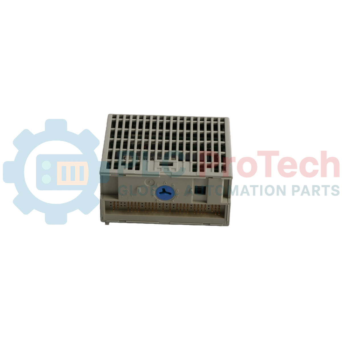
Keyswitch Position
Position 7
Operating Temperature
-20...+70 degC (-4...+158 degF)
Storage Temperature
-40...+85 degC (-40...+185 degF)
Relative Humidity
5...95% noncondensing
Operating / Nonoperating Shock
Tested to 15 g peak acceleration, 11(+1) ms pulse width
Vibration
Tested 2 g @ 10...500 Hz per IEC68-2-6
Dimensions (H x W x D)
46 x 94 x 75 mm (1.8 x 3.7 x 2.95 in.)
Weight
Approx. 200 g (7.05 oz.)
Connections/Interfaces
Terminal Pin
Function
Row A - Terminal 0
Output 0 Channel (+) Connection
Row A - Terminal 1
Output 0 Channel (-) Connection
Row A - Terminal 4
Output 1 Channel (+) Connection
Row A - Terminal 5
Output 1 Channel (-) Connection
Row A - Terminal 8
Output 2 Channel (+) Connection
Row A - Terminal 9
Output 2 Channel (-) Connection
Row A - Terminal 12
Output 3 Channel (+) Connection
Row A - Terminal 13
Output 3 Channel (-) Connection
Row C - Terminal 34
+V DC Intrinsically Safe Power Input
Row C - Terminal 35
-V DC Intrinsically Safe Power Common Input
Row C - Terminal 50
+V DC Power Daisy-Chain Extension Terminal
Row C - Terminal 51
-V DC Power Common Daisy-Chain Extension Terminal
Note: Terminals 2, 3, 6, 7, 10, 11, 14, 15, 17 to 32, 36, 37, 38, 39, 46, 47, 48, and 49 are unused and no connections are permitted. Do not use unused terminals as supporting terminals to avoid system damage.
InstallationGuidelines
Enclosure Specifications: The module must be installed within a suitably rated metal enclosure when used in Zone 1 to protect it from environmental exposure, as the module itself holds an IP20 factor rating.
Zone 22 Cabinet Selection: For installation within Zone 22 dust environments, specific certified cabinet models must be utilized: IVK-ISRPI-V16LC, IVK-ISRPI-V8HYW, or IVK-ISRPI-V8LC.
Keyswitch Alignment: Before mounting the module, rotate the keyswitch on the terminal base unit clockwise to position 7. Do not alter this keyswitch setting once wiring configuration is finished.
FlexBus Setup: Ensure that the FlexBus connector is pushed completely to the left toward the neighboring base unit or adapter before trying to insert the module; execution is blocked unless fully extended.
Pin Alignment and Seating: Verify all bottom connection pins are straight, align the module's alignment bar with the alignment groove on the base, and press down firmly until the latching mechanism securely locks.
Intrinsically Safe Separation: Only join intrinsically safe terminal bases to other intrinsically safe system modules/adapters to secure backplane integrity.
Shielding and Grounding: All I/O wiring must use high-quality shielded wire. All wire shields must be terminated strictly external to the module using dedicated bus bars or shield-terminating feed-through points.
Electrostatic Prevention: The entire system must be protected against electrostatic charges. Install a highly visible warning sign in immediate proximity stating: "WARNING Avoid electrostatic charging".
Power Restrictions: The system must be powered exclusively by an intrinsically safe power supply. Never allow nonintrinsically safe signals to be applied to the module, as doing so permanently invalidates its intrinsic safety status.
Live Insertion Rules: Although the module supports removal and insertion under power, an electrical arc can occur if the underlying terminal base is unseated or wired while field power is live, posing an explosion risk in hazardous areas. Ensure power is fully isolated or that the environment is verified nonhazardous before handling.
ComplianceandCertifications
CENELEC: II (1) 2G Ex ib[ia] IIC T4, II (1) D [Ex iaD]
UL, C-UL: Certified for Class I, Groups A, B, C, D; Class II, Groups E, F, G; Class III Hazardous Locations; Class I, Zone 1, AEx ib[ia] IIC T4
FM: Intrinsically Safe Class I, Div 1, Groups A, B, C, D, T4; Associated Apparatus with intrinsically safe connections Class I, II, III, Div 1, Groups A-G; Class I, Zone 1, AEx ib[ia] IIC T4
ATEX: Reference Certificate Number DMT 02 ATEX E 040 X complying with EN 60079-0, EN 60079-11, and EN 61241 series
CE Mark Directives: Approved for installation within the EU and EEA regions under EMC Directive 2014/30/EU applying EN 61000-6-4:2007, EN 61000-6-2:2005, and EN 61326-1:2013
FAQ
What terminal bases are compatible with the 1797-OB4D module?
The module must be used exclusively with the 1797-TB3 or 1797-TB3S intrinsically safe terminal base units.
What does a solid red status LED indicate on the front panel?
A solid red indicator means the module did not pass its power-up check routine.
Can this module be repaired if a single channel fails?
No, this module is not field-repairable. Attempting to open the enclosure voids the factory warranty and its intrinsic safety certifications.
What is the default operation state of the outputs upon initial power-up?
At system power-up, the Output Enable bit is default set to 0, which keeps all outputs forced off until initialized to 1 via the application program.
What range of field load resistance is supported for normal operation?
The normal load range per channel is defined as 30 to 5000 Ohm.
How does the module signal a wire-off or channel overload fault?
Faults are signaled via the internal data table fault bits and by the corresponding channel LED flashing red at a 1 Hz frequency.
Is it safe to use this module with standard non-intrinsically safe signals?
No, you must never apply non-intrinsically safe signals. The module cannot be reused in an intrinsically safe environment once exposed to non-intrinsically safe signals.
What happens if I wire field devices to the unused terminals of the base?
Using unused terminals as supporting terminals can cause severe physical damage to the module, unintended system operations, or both.
What is the maximum signal propagation delay time for channel state changes?
The maximum output delay time for both OFF-to-ON and ON-to-OFF transitions is less than 1.2 ms.
Are the output channels isolated from each other?
No, the channels in this module are non-isolated and are electrically connected to each other.
Can this module be inserted into a live terminal base while the backplane is powered?
Yes, it is designed for hot-swapping, but field-side power must be removed or the area verified nonhazardous to avoid an explosion from an electrical arc.
What is the purpose of the Latch Alarms configuration parameter?
It dictates whether a wire-off or overload fault bit remains locked until manually cleared by a Reset Alarms transition, ensuring short-duration faults are captured.
What threshold guarantees a wire-off fault is reported?
A wire-off condition is guaranteed to be flagged and reported for field loads greater than 75 kOhm, regardless of output state.
How are the fault alarm filters configured in software?
The Alarm Filter bits allow setting the time constant across a range of binary options: 0.25 ms, 0.5 ms, 1 ms, 2 ms, 4 ms, 8 ms, 16 ms, or 32 ms.
Maintenance data connects work orders, sensor signals, asset history, costs, and technician knowledge. Used well, it improves planning, reliability, predictive maintenance, spare-parts control, and...
This article explains how integrated electric actuators, such as SMC’s e-Actuator series, are transforming industrial motion control by replacing traditional pneumatic and hydraulic systems. It...
This article explains how PLC systems perform core mathematical operations such as addition, subtraction, multiplication, division, modulo, and exponentiation within industrial automation. It shows...
The article explains several advanced Boolean logic functions used in PLC programming beyond basic AND, OR, and NOT operations. It covers how tools like truth tables, multiplexers, pulse generators,...
Boolean logic is the foundation of every PLC program. From simple machine controls to complex industrial automation systems, logic gates determine how controllers respond to changing inputs and...
Industrial firewalls play a critical role in OT cybersecurity, protecting PLC, DCS, and SCADA networks through segmentation, ingress/egress control, and IDS/IPS integration aligned with IEC 62443...
Choosing a selection results in a full page refresh.