


Replacing ABB DSQC 351: Controller and Network Checks
Checks to record before replacing ABB 3HNE 00006-1 DSQC 351: controller generation, X3/X5/X20/X21 wiring, DeviceNet settings, INTERBUS mapping, and LED states.
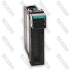
Manufacturer: Allen-Bradley
Product No.: 1756-OB16IS
Country of origin:United States
Product Type: Digital Output Module
Barcode: 8537101190
Payment: T/T, Western Union
Weight: 200g
Dimensions: 3.5cm x 14.2cm x 14.5cm
Shipping port: Xiamen
Warranty: 12 months
The 1756-OB16IS is a digital output execution component built for the ControlLogix system configuration. It functions within a nominal 12/24V DC voltage envelope, featuring 16 channels that are isolated individual points designed to secure downstream circuitry against cross-signal disturbance and transient spikes. This module integrates 8 scheduled output points designed to enable precise synchronization matching coordinated machine sequences with reference to the Coordinated System Time. It installs inside standard control slots, interfacing with industrial field loads via specified removable termination assemblies to provide deterministic actuation and steady processing states under multiple manufacturing control configurations.
| Parameter | Specification |
|---|---|
| Outputs | 16 individually isolated, 8 scheduled |
| Pilot Duty | 2 A (DC-13SQ) |
| Voltage Category | 12/24V DC sink/source |
| Operating Voltage Range | 10...30V DC |
| Output Delay Time (Off to On) | 1 ms max |
| Output Delay Time (On to Off) | 2 ms max |
| Current Draw @ 5.1V | 350 mA |
| Current Draw @ 24V | 2.5 mA |
| Total Backplane Power | 1.8 W |
| Power Dissipation, Max | 3.6 W @ 60 degC (140 degF) |
| Thermal Dissipation | 12.28 BTU/hr |
| Off-State Leakage Current Per Point, Max | 0.5 mA per point |
| On-State Voltage Drop, Max | 1.2V DC @ 2 A |
| Current Per Point, Max | 2 A @ 30 degC (86 degF), 1 A @ 60 degC (140 degF) (linear derating) |
| Current Per Module, Max | 8 A @ 30 degC (86 degF), 4 A @ 60 degC (140 degF) (linear derating) |
| Surge Current Per Point | 4 A for 10 ms per point, repeatable every 2 s |
| Load Current, Min | 1 mA per point |
| Scheduled Outputs Synchronization | Within 16.7 s max, reference to the Coordinated System Time |
| States in Fault Mode Per Point | Hold last state, On or Off (Off is default) |
| States in Program Mode Per Point | Hold last state, On or Off (Off is default) |
| Isolation Voltage | 250V (continuous), basic insulation type, outputs-to-backplane, and output-to-output |
| Module Keying | Electronic, software configurable |
| Removable Terminal Block | 1756-TBCH, 1756-TBS6H |
| RTB Keying | User-defined mechanical |
| Slot Width | 1 |
| Wire Category | 1 |
| Wire Type | Copper |
| Enclosure Type | None (open-style) |
| Temperature, Operating | 0...60 degC (32...140 degF) |
| Temperature, Nonoperating | -40...85 degC (-40...185 degF) |
| Relative Humidity | 5...95% noncondensing |
| Vibration | 2 g @ 10...500 Hz |
| Shock, Operating | 30 g |
| Shock, Nonoperating | 50 g |
| Emissions | IEC 61000-6-4 |


Global Express Shipping
Returns & Warranty


| Product Image | Model Number / Title | Condition | Availability | Action |
|---|---|---|---|---|

|
Allen-Bradley 1746-OVP16 SLC 500 Digital DC Output Module | Original New | In Stock | View Details |
|
Allen-Bradley 1756-OB8 ControlLogix DC Digital Output Module | Original New | In Stock | View Details |

|
Allen-Bradley 1794-OB16P FLEX I/O Digital DC Output Module | Original New | In Stock | View Details |
Global Express Shipping
Returns & Warranty
Orders are processed and delivered Monday-Friday (excluding public holidays).
For full eligibility, restocking fees, and international return details, please view our official Refund & Return Policy .
| Color pattern |
Black
|
| Country of origin |
United States
|
| Power source |
DC Power
|

Checks to record before replacing ABB 3HNE 00006-1 DSQC 351: controller generation, X3/X5/X20/X21 wiring, DeviceNet settings, INTERBUS mapping, and LED states.

Compare the IC693CPU360 and IC693CPU364 by Ethernet interface, +5 VDC load, memory, rack limits, and replacement checks.

A field-first diagnostic sequence for 1756-OF4 analog output problems: channel mode, removable terminal block, scaling, and controlled electrical checks.

A direct comparison of 1746-OA8 and 1746-OA16 output count, common grouping, backplane current and temperature-derated load limits.

A field checklist for recording the 1761-NET-DNI hardware series, firmware, EDS file, DF1 settings, DeviceNet address and messaging configuration before replacement.

The EL3062 is a 0–10 V EtherCAT terminal. The EL3062-0030 is a 0–30 V variant. This checklist covers identification, scaling and commissioning.