Allen-Bradley

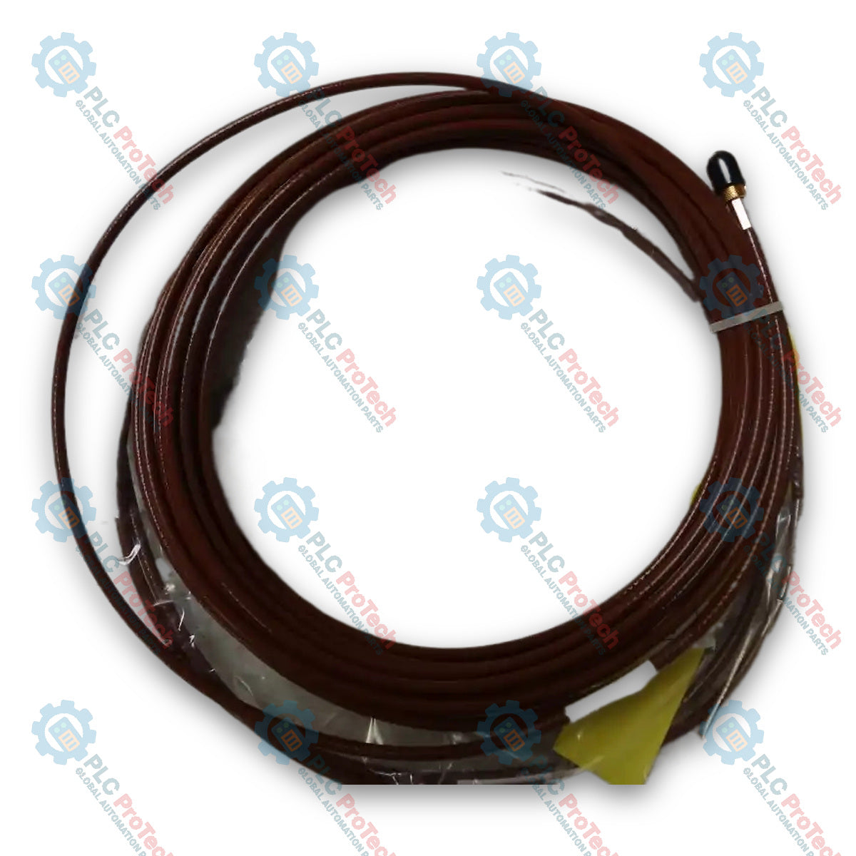
Allen-Bradley EK-2110-30-05-1-10 2100 Series Non-contact Eddy Current Probe

SKU EK-2110-30-05-1-10

In stock
  • 12-month warranty
  • Free returns within 30 days
  • Manufacturer: Allen-Bradley

  • Product No.: EK-2110-30-05-1-10

  • Country of origin:United States

  • Product Type: Eddy Current Probes

  • Payment: T/T, Western Union

  • Weight: 150g

  • Dimensions: 150 mm x 100 mm x 30 mm (H x W x D)

  • Shipping port: Xiamen

  • Warranty: 12 months

Description

The Allen-Bradley EK-2110-30-05-1-10 is an 8 mm (0.31 in.) tip diameter reverse mount non-contact pick-up probe belonging to the 2100 Series Eddy Current Probe Systems. This probe introduces eddy currents into a target material to read relative position by measuring energy loss changes as the target surface moves, supplying a modulated voltage output proportional to the gap between the probe tip and the target. Designed for non-contact measurement in speed and acceleration monitoring applications, the device features an M10x1 threaded body with a 30 mm (1.18 in.) body length and 5 mm (0.20 in.) unthreaded length, equipped with a 1.0 m (3.28 ft) standard Teflon-insulated sensor cable and a stainless steel, gold-plated SMA connector. Operating within a 2100 series system, the probe connects through an extension cable to a case-isolated, panel-mounted driver that conditions the radio frequency signal and maintains linearity over its operating range.

Features

  • Reverse Mount Configuration: Features reverse mount housing with an M10x1 body thread and a 30 mm (1.18 in.) body length.
  • 8 mm Probe Tip: Engineered with an 8 mm (0.31 in.) tip diameter, suitable for speed and acceleration applications.
  • Standard Cable: Integrated with a 1.0 m (3.28 ft) standard unarmored Teflon-insulated coaxial cable.
  • Gold-Plated Connector: Terminated with a gold-plated stainless steel SMA connector.
  • High-Temperature Resistance: Rated for probe sensor operation across a temperature range of -40 to 177 degC (-40 to 350 degF).

Applications

  • Machinery speed and acceleration measurement
  • Non-contact shaft relative position sensing
  • 2100 Series eddy current proximity transducer measurement systems

Technical Specifications

Parameter Specification
Manufacturer Allen-Bradley / Rockwell Automation
Model EK-2110-30-05-1-10
Product Series 2100 Series
Product Type Non-contact Eddy Current Pick-up Probe
Mounting Type Reverse Mount
Tip Diameter 8 mm (0.31 in.)
Thread Size M10x1
Body Length 30 mm (1.18 in.)
Unthreaded Length 5 mm (0.20 in.)
Cable Type Standard Cable (Unarmored Teflon)
Sensor Cable Length 1.0 m (3.28 ft)
Linear Range (Approx.) 8 to 188 mils (0.2 to 4.7 mm)
Sensitivity 200 mV/mil (787 mV/100 µm) (at 25 degC with -24V DC supply, 10 kΩ load, AISI 4140 steel target)
Linearity ±0.8 mils of 200 mV/mil (if calibrated as a system)
Frequency Response DC to 10 kHz (-3 dB)
Connector Type Stainless steel, gold-plated SMA connector
Connector Tip Diameter (Max) 9.5 mm (0.37 in.)
Sensor Operating Temperature -40 to 177 degC (-40 to 350 degF)
Operating Humidity 30 to 95% RH (noncondensing, nonsubmerged)

Installation Guidelines

  • System Integration: Connect the probe via a matching 2100 series extension cable to a panel-mounted 2100 series driver; note that 2100 series drivers are not case-isolated and require an isolating pad or mounting inside an isolated enclosure.
  • Driver Power Supply: System operates with a driver supply voltage range of -17.5 to -26V DC.
  • Signal Wiring: Use 0.82 to 2.08 mm² (18 to 14 AWG) shielded 3-conductor instrumentation wire to connect the driver to the monitoring system. Limit total field cable distance to 300 m (984 ft) to ensure 0 to 10 kHz frequency response transmission with minimal attenuation.
  • Shield Grounding: Ensure the cable shield is grounded at a single point, typically at the monitoring instrument.

Compliance and Certifications

  • CSA: System Ex ia IIC T4, AEx ia IIC T4, Class I Zone 0/1 or Class I Division 1; Groups A, B, C, D (when installed with safety barriers per drawing ETK51271-HAZ, sheet 1); Class I Division 2 Groups A, B, C, D without barriers per ETK51270-HAZ.
  • CE: European Union EMC Directive 2004/108/EC.
  • C-Tick: Australian Radio Communications Act, compliant with AS/NZS 2064 Industrial Emissions.
  • ATEX: European Union ATEX Directive 94/9/EC II 1 G, Ex ia IIC T4 (EC certificate LCIE 07 ATEX 6051 X).
  • API Standard: API 670 compliant in all respects except for tolerance to environments containing hydrogen sulfide and ammonia.

FAQ

What is the Allen-Bradley EK-2110-30-05-1-10 used for?

The Allen-Bradley EK-2110-30-05-1-10 is a 2100 Series 8 mm non-contact reverse mount eddy current probe used for non-contact measurement of speed and acceleration in industrial rotating machinery.

Which product series does the EK-2110-30-05-1-10 belong to?

The EK-2110-30-05-1-10 belongs to the Allen-Bradley 2100 Series Eddy Current Probe Systems.

What are the mechanical dimensions and mounting specifications for the EK-2110-30-05-1-10?

The device features an 8 mm (0.31 in.) probe tip, reverse mount housing, an M10x1 thread, a body length of 30 mm (1.18 in.), an unthreaded length of 5 mm (0.20 in.), and a 1.0 m (3.28 ft) standard cable.

What operating temperature range is the probe sensor rated for?

The probe sensor element is rated to operate in ambient temperatures ranging from -40 to 177 degC (-40 to 350 degF).

View all FAQs →

Product Documentation

Technical Datasheet (PDF) Complete specifications and technical drawings.

Technical Datasheet

Allen-Bradley EK-2110-30-05-1-10 2100 Series Non-contact Eddy Current Probe

Quantity
Shipping & Returns

Global Express Shipping

  • Standard Delivery: 4–6 business days via DHL, FedEx, and UPS.
  • Express Dispatch: Same-day dispatch for in-stock orders placed before 2:00 PM (GMT+8).
  • Worldwide Coverage: Serving over 150 countries.

Returns & Warranty

  • 30-Day Guarantee: Returns accepted for in-stock products in original, factory-sealed packaging.
  • 12-Month Warranty: Every industrial component is backed by our technical warranty.
Reviews
1 of 1
Only 10 item(s) left in stock
Quantity
View full details

Global Express Shipping

  • Standard Delivery: 4-6 Business Days via DHL, FedEx, and UPS.
  • Express Dispatch: Same-day dispatch for in-stock orders placed before 2:00 PM (GMT+8).
  • Worldwide Coverage: Serving over 150 countries, including rapid delivery to Saudi Arabia and UAE.

Returns & Warranty

  • 30-Day Guarantee: Returns accepted for in-stock products in original, factory-sealed packaging.
  • 12-Month Warranty: Every industrial component is backed by our professional technical warranty.

Orders are processed and delivered Monday-Friday (excluding public holidays).


For full eligibility, restocking fees, and international return details, please view our official Refund & Return Policy .

TECHNICAL SPECIFICATIONS

Country of origin
United States

Technical knowledge

Electromagnetic Induction in Industrial Coils

Understand how industrial coils create magnetic force, induce voltage, generate switching transients, and fail in relays, solenoids, transformers, motors, and proximity sensors. in service.

Designing Power and Communication Redundancy

Design control-system redundancy by mapping shared dependencies, separating power and network paths, defining failover behavior, exposing degraded operation, and proof-testing every tolerated fault.

Troubleshooting Industrial Control Cabinets Systematically

A structured control-cabinet troubleshooting method covering safe work, drawings, power paths, branch protection, DC supplies, return circuits, PLC outputs, fault records and repair verification.

Measuring Voltage in Industrial Control Circuits

A practical voltage-testing guide for industrial control panels, covering reference points, meter selection, live-dead-live checks, voltage drop, ghost voltage, stored energy and intermittent faults.

Building a Verifiable Lockout Tagout Procedure

A practical lockout tagout guide covering hazardous-energy identification, isolation, stored-energy control, verification, group work, temporary testing, restoration, inspections and audits.

Designing Compressed-Air Preparation at the Machine

A field guide to point-of-use compressed-air preparation covering filters, regulators, drains, dryers, lubrication, pressure loss, isolation, monitoring, commissioning and leak testing.