Industrial Power Control Overview
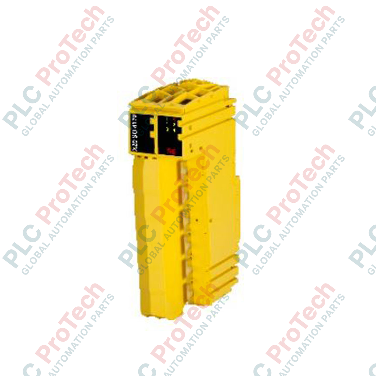
The B&R 20SO4110 (20SO4110) is a ruggedized industrial digital output module designed for the heritage B&R System 2005 automation platform. Deployed primarily within continuous-operation manufacturing sectors such as plastics extrusion machinery, heavy material conveyor systems, and traditional power plant auxiliary controls, this module manages high-reliability discrete switching networks. By interfacing directly between the centralized processor and field-level actuators (including heavy-duty solenoids, interposing relay coils, and magnetic contactors), the module maintains excellent signal isolation and rapid switching performance, protecting the system from operational downtime.
Output Architecture and Operational Reliability
This discrete card features a high-density configuration optimized for backplane integration within standard System 2005 rack assemblies. The internal solid-state components are designed to withstand industrial electrical transients and sudden load fluctuations typical of factory floors. Built using dense, high-durability circuitry, the module delivers consistent current sourcing capabilities across all active channels simultaneously, eliminating voltage sags on the control bus and ensuring predictable actuation speeds for downstream field hardware.
Technical Performance Matrix
| Hardware Parameter |
Specification Details |
| Model |
20SO4110 |
| Brand |
B&R (System 2005 Platform) |
| Origin |
Austria |
| Module Classification |
Discrete Digital Output Module |
| I/O Configuration |
Multi-channel solid-state outputs |
| Control System Compatibility |
Automation Studio / System 2005 Bus |
| Operating Temperature |
0 to 55 deg C (Standard vertical rack layout) |
| Storage Temperature |
-25 to 85 deg C |
| Relative Humidity Range |
5 to 95% (Non-condensing) |
| Net Weight |
0.45 kg |
| Shipping Gross Weight |
2.0 kg (Including heavy industrial packaging) |
System Integration and FAQs
What are the primary indicators of an output hardware fault on the 20SO4110?
The faceplate of the 20SO4110 features dedicated diagnostic LEDs for channel status tracking. If an active command is sent from the PLC logic but the corresponding channel LED remains unlit or displays a fault pattern, check the external field fuse and confirm that the incoming 24 VDC auxiliary power rail is sitting within standard tolerances.
Can this module be hot-swapped while the System 2005 rack is energized?
No. The System 2005 bus architecture requires the main backplane power supply to be completely de-energized prior to inserting or removing any I/O cards. Attempting to swap the 20SO4110 while power is live can cause voltage arcs across the gold backplane fingers, resulting in irreversible hardware damage to the module or adjacent processor cards.
How should unused output channels be handled in the control program?
Unused channels on the 20SO4110 can simply be left disconnected at the physical terminal block. In the software environment (Automation Studio), these channels do not require explicit mapping or termination, and leaving them unmapped will not trigger any backplane bus faults or diagnostic errors.
Field Commissioning and Wiring Guidelines
-
Inductive Load Suppression: When using the outputs to drive inductive loads such as heavy solenoids, mechanical clutches, or contactors, install external flyback diodes (for DC circuits) or RC snubbers (for AC circuits) directly across the load terminals. This step suppresses inductive voltage spikes at the source, preventing long-term degradation of the module's internal solid-state switches.
-
Backplane Cleanliness and Seating: Prior to sliding the module into the System 2005 slot, visually inspect the backplane connector for any airborne dust or particulate buildup. Guide the module firmly into the rack until the top and bottom mechanical locking tabs click into position, ensuring a low-resistance connection to the logic bus.
-
Enclosure Thermal Management: Ensure the electrical enclosure maintains adequate airflow to keep the ambient temperature around the rack assembly below 55 deg C. Maintain a minimum vertical clearing of 50 mm above and below the card cage to promote natural convection cooling and prevent localized thermal hotspots.