Network Architecture Overview
The B&R X20BM05 (X20BM05) is a highly specialized hardware base bus module designed for the modular B&R X20 automation ecosystem. Implemented across complex multi-node production facilities, chemical processing plants, and distributed marine control topologies, this bus module functions as the structural and electrical foundation for all X20 supply modules. By integrating physical node number switches directly into the backplane base, the unit decouples node address identification from the hot-swappable electronic modules. This design guarantees consistent network device mapping, simplifies maintenance sequencing, and prevents configuration mismatches during component changeouts.
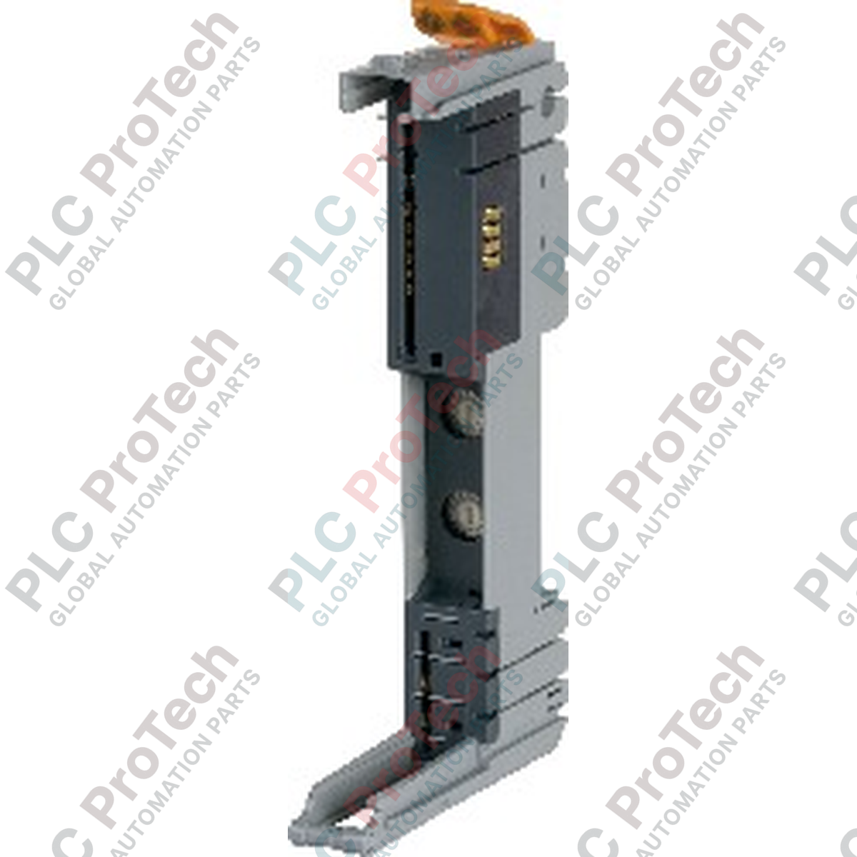
Segment Isolation and Addressing Capabilities
The X20BM05 is engineered to establish isolated voltage groups within a standard I/O rack. Its primary electrical feature is a physical interruption barrier that isolates the internal I/O power supply lines to the left of the module. This layout enables engineers to divide a single physical rack into distinct, independent potential segments to handle emergency shutdown loops or separate field instrument groups safely. The module includes two integrated rotary switches for manual decimal node number assignment, which can be combined seamlessly with automatic addressing parameters inside B&R Automation Studio.
Technical Performance Matrix
| Hardware Parameter |
Operational Specification |
| Model |
X20BM05 |
| Brand |
B&R Automation |
| Origin |
Austria |
| Module Classification |
Power Supply Base Bus Module |
| Hardware Keying |
24 VDC mechanical keying |
| Bus Segment Boundary |
Internal I/O power supply isolated to the left |
| Addressing Topology |
Manual node number assignment via hardware switches |
| Nominal Voltage Profile |
24 VDC |
| Permissible Contact Load |
10 A maximum backplane capacity |
| Internal Bus Power Consumption |
0.13 W |
| Module Width (Pitch) |
12.5 mm (+0.2 mm manufacturing tolerance) |
| Horizontal Temperature Limits |
-25 to 60 deg C |
| Vertical Temperature Limits |
-25 to 50 deg C |
| Humidity Constraints |
5 to 95% Relative Humidity (Non-condensing) |
| Net Structural Weight |
0.05 kg |
| Shipping Gross Weight |
2.0 kg (Including rigid transport packaging) |
System Integration and FAQs
What is the functional purpose of isolating the internal I/O power supply to the left?
The isolation design prevents 24 VDC voltage from crossing backplane lines into any modules mounted to the immediate left of the X20BM05. This feature creates a distinct voltage zone boundary, allowing maintenance teams to isolate, de-energize, or modify field devices on the right side of the rack without interrupting the electrical supply of equipment configured on the left.
How does altitude affect the thermal operating profile of this bus module?
For installation elevations between 0 and 2000 meters above sea level, the module operates normally without environmental restrictions. For deployment locations exceeding 2000 meters, thin-air conditions reduce natural heat dissipation; therefore, the maximum permissible ambient operating temperature must be derated by 0.5 deg C for every 100 meters of additional elevation.
Can an electronics module be replaced while the system address switches are being adjusted?
Yes. Because the rotary address switches are located directly on the X20BM05 hardware base rather than on the plugged-in electronics module, the active node network ID remains fixed to the specific DIN rail position. If an electronic failure occurs, the top processing module can be replaced while keeping the physical address intact.
Field Commissioning and Installation Directives
-
Node Switch Addressing Alignment: Set the two rotary decimal switches using a small flat-head screwdriver prior to clipping the top electronics module into place. Ensure the tens and units dials accurately reflect the specific node address assigned within the master controller's hardware configuration tree to prevent node conflict errors on the fieldbus network.
-
Backplane Current Management: Ensure that the cumulative current consumption of all downstream I/O cards drawing power from this potential zone does not exceed the strict 10 A permissible contact load limit. Running calculations that cross this threshold will cause premature thermal degradation of the internal gold-plated bus clips and trigger intermittent bus failures.
-
DIN Rail Mounting Tolerances: When latching multiple modules together, maintain a stable mounting plane. The structural 12.5 mm pitch relies on perfect perpendicular alignment on standard TS35 DIN rails. Ensure the rail is clean and free of distortions, and install rugged mechanical end clamps at both ends of the finished assembly to prevent lateral module separation.