Processing Power and Industrial Application
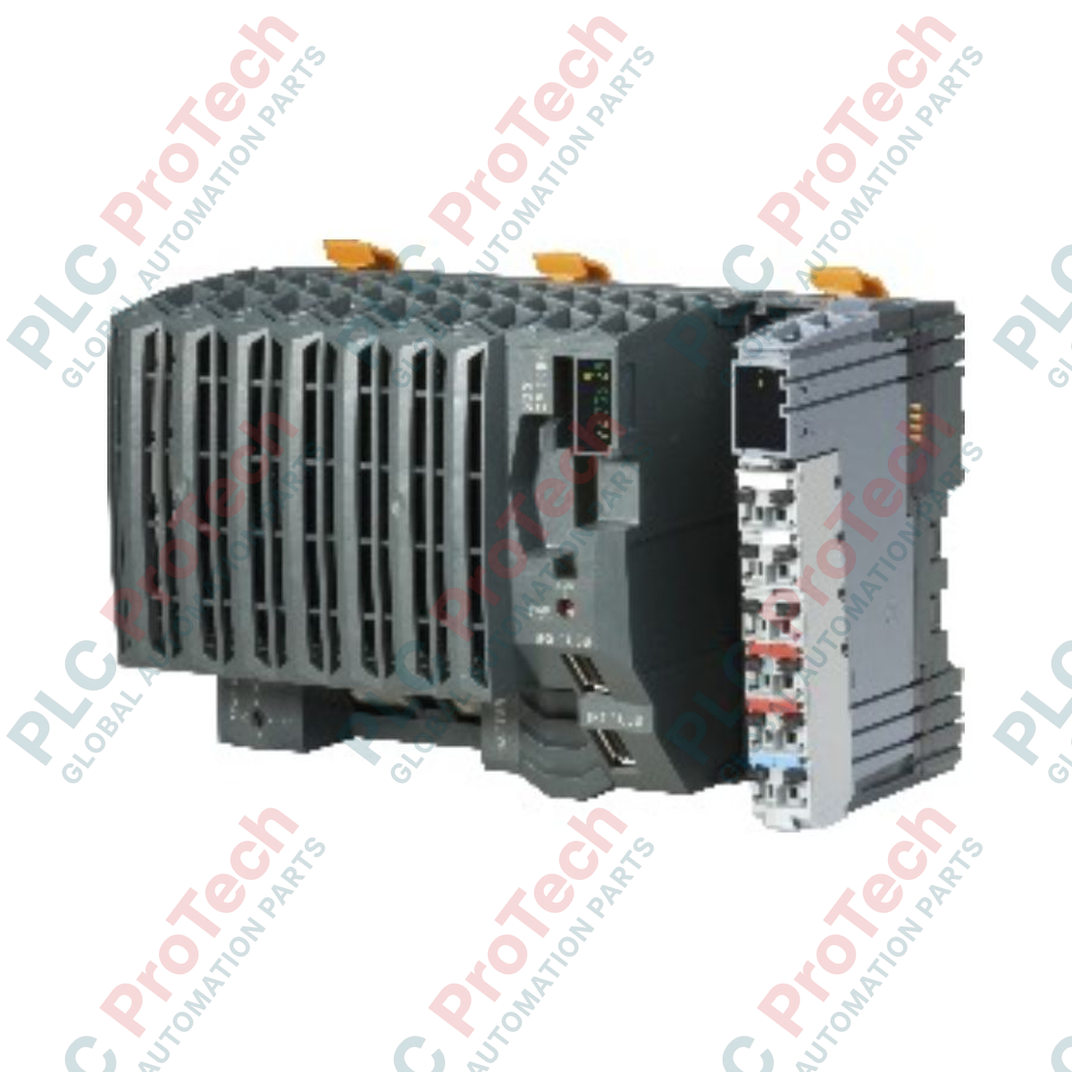
The X20CP1484-1 (X20CP1484-1) is a high-performance industrial CPU controller designed to serve as the master processing unit for complex B&R X20 automation architectures. Tailored for heavy-duty process control, high-speed material handling, power generation monitoring, and complex manufacturing lines, this embedded controller executes synchronous motion control and precise logic computation. It features a fan-free cooling design, which eliminates mechanical wear points and prevents inner component failure caused by airborne particulate matter. Implementing this robust controller into your central control system establishes a highly resilient architecture that minimizes cyclical scan times, reduces communication latency, and protects critical infrastructure against unmanaged process halts.
System Infrastructure and Network Interface
Built on an efficient Celeron 266 compatible processor core backed by 64 MB of integrated high-speed SDRAM, this CPU handles concurrent task management with predictable execution patterns. The hardware provides a comprehensive networking matrix, hosting one RS232 interface for legacy serial connections, one standard Ethernet port for corporate network integration, two USB slots for local system management, and an X2X Link bus master interface for local I/O expansion. Additionally, the unit incorporates an onboard real-time Ethernet POWERLINK (V1/V2) connection, allowing high-precision synchronization of remote drives and distributed I/O blocks. System monitoring is maintained via local status indicators that give instant diagnostics for CPU function, overtemperature states, Ethernet connectivity, POWERLINK status, CompactFlash access, and backup battery charge.
Comprehensive Technical Specifications
| System Parameter |
Engineered Value |
| Model |
X20CP1484-1 |
| Brand |
B&R (Bernecker + Rainer) |
| Product Category |
Embedded CPU Module |
| Processor Architecture |
Celeron 266 compatible |
| System Memory (RAM) |
64 MB SDRAM |
| Integrated Communication Interfaces |
1x RS232, 1x Ethernet, 1x POWERLINK V1/V2, 2x USB, 1x X2X Link |
| Cooling Method |
Fan-free convection cooling |
| Input Supply Voltage |
24 VDC (-15% / +20% variance limit) |
| Maximum Input Current |
2.2 A |
| Rated Bus Output Voltage |
24 VDC |
| Permitted Contact Load |
10.0 A |
| Typical Power Dissipation |
10.5 W |
| Storage Medium Support |
CompactFlash card slot |
| Dimensions (W x H x D) |
150 x 99 x 85 mm |
| Net Device Weight |
0.7 kg |
| Gross Shipping Weight |
2.0 kg (Including robust transit packaging) |
Engineering Diagnostics FAQ
What should be done when the overtemperature LED status indicator turns red?
An active overtemperature indicator signals that the internal CPU temperature has surpassed safe operating parameters. Immediately verify that cabinet ventilation channels are clear, ensure the fan-free heat sink fins are free from dust accumulation, and confirm that adjacent hardware is not exceeding thermal radiation guidelines.
How is the real-time operating system and application program stored on this module?
The X20CP1484-1 utilizes a dedicated CompactFlash card slot for system boot operations. The Automation Runtime operating system, configuration parameters, and compiled application programs are stored directly on the card, enabling fast controller replacement without needing a separate laptop download.
Can the X2X Link interface power remote I/O nodes directly?
The integrated X2X Link interface acts as the bus master and provides signal communications. While it manages the data flow, remote I/O nodes situated further down the rail or across extended distances require separate X20 system power supply modules to compensate for bus line voltage drops.
Field Commissioning and Deployment Guidelines
-
Firmware and Program Backup Management: Before executing live commissioning routines via B&R Automation Studio, insert an industrial-grade CompactFlash card formatted with the correct Automation Runtime partition. Maintain an identical backup card inside the control enclosure to facilitate immediate recovery in the event of an unexpected localized memory hardware failure.
-
Power Distribution Safety Boundaries: Connect the incoming 24 VDC supply through a dedicated, filtered industrial power supply network. Because the CPU can draw up to 2.2 A during peak processing and bus startup cycles, use properly sized conductors and place a fast-acting fuse upstream to safeguard the internal electronics against voltage surges.
-
Earthing and Mechanical Installation Verification: Snugly mount the CPU module onto the DIN rail interface, ensuring all grounding clips establish a low-impedance connection with the grounded metallic backplane. Tighten all communication cables and shield terminations to mitigate the risk of high-frequency electrical noise corrupting the high-speed POWERLINK loop.