Technical Description and Functional Role
The X20IF2772 (X20IF2772) is a dedicated interface communication module designed for direct slot integration into a B&R X20 CPU system. Engineered to expand the networking capabilities of local controllers in complex automation networks—such as municipal water treatment, petrochemical processing, and automated assembly lines—this module establishes a reliable data bridge between the primary controller and auxiliary field devices. Operating with an optimized internal processor architecture, the module manages dedicated fieldbus communication routines independently, offloading the primary CPU from network stack overhead. Integrating this industrial communication interface into your rack configuration guarantees deterministic data exchange rates, protects against packet degradation, and cuts unexpected machine communication timeouts.
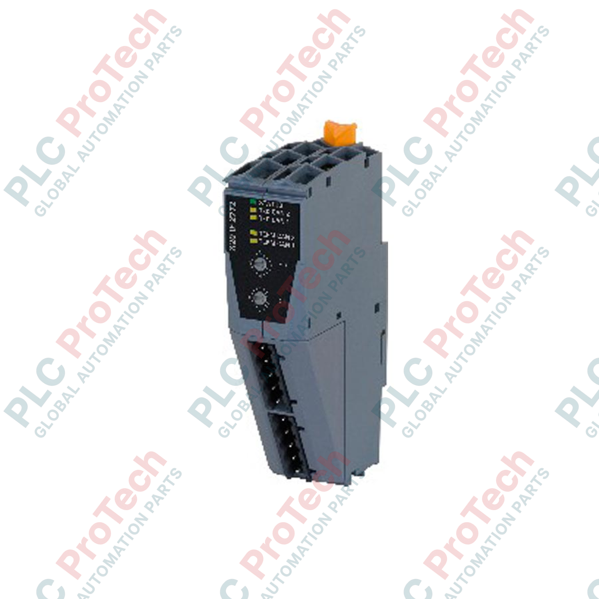
Diagnostics and Interface Architecture
Carrying the official B&R ID code 0x1F25, this module features built-in hardware diagnostics that provide real-time status tracking via localized LED indicators. The interface configuration gives engineers instant visual confirmation across three critical parameters: overall module health status, active data transfer cycles, and the current state of the integrated terminating resistor. Operating with a low thermal signature, the module consumes a maximum of 1.2 W from the system bus, preserving power balance for adjacent I/O modules on the same node. The physical interface requires two TB2105 terminal blocks (ordered separately) to secure field cabling directly to the plug-in module surface.
Functional Performance Specifications
| Interface Parameter |
Engineered Specification |
| Model |
X20IF2772 |
| Brand |
B&R (Bernecker + Rainer) |
| Module Category |
X20 System Communication Interface |
| B&R ID Code |
0x1F25 |
| Compatible Slot |
Direct integration slot in X20 CPU |
| Power Consumption |
Max. 1.2 W |
| Module Status Diagnostics |
Integrated LED status indicator |
| Data Transfer Diagnostics |
Integrated LED status indicator |
| Terminating Resistor Diagnostics |
Integrated LED status indicator |
| Required Terminal Hardware |
2x Terminal Block TB2105 (not included) |
| Isolation Barrier |
Galvanic isolation between network and CPU |
| Operating Humidity Limits |
5 to 95% non-condensing |
| Storage Temperature Bounds |
-25 to 55 deg C |
| Country of Origin |
Austria |
| Gross Shipping Weight |
1.0 kg (Including protective anti-static packaging) |
Engineering Integration FAQ
Where exactly inside the X20 rack is the X20IF2772 installed?
The X20IF2772 is not an I/O slice module; it is specifically designed to fit into the dedicated interface slot located directly on the housing of an X20 CPU controller. Power and data bus pathways are established through the CPU backplane connection.
What is the purpose of the terminating resistor LED indicator?
The terminating resistor LED provides active verification of physical line termination status. In long-distance industrial networks, improper termination causes signal reflection and packet corruption; this indicator ensures field technicians can instantly spot incorrect line configuration.
Can this module run without the TB2105 terminal blocks?
The module electronics will power up inside the CPU slot, but you cannot connect physical communication lines without the terminal blocks. You must source two separate TB2105 terminal blocks to execute network wiring terminations.
Field Commissioning and Deployment Guidelines
-
Bus Segment Termination Protocol: When positioning this interface module at the physical end of a communication network line, engage the terminating resistor via your system configuration software. Check that the physical terminating resistor LED illuminates to verify the internal resistive network is shielding the line against electrical noise.
-
Module Insertion Safety Standards: Always isolate power to the parent X20 CPU before inserting or extracting the X20IF2772 module from its interface slot. Handling the interface hardware while the bus is powered can cause micro-arcing across the backplane pins, causing data corruption or chip damage.
-
Terminal Cable Shielding Alignment: When preparing communication cables for the TB2105 terminal blocks, strip back the outer jacket and ground the braided shield completely to the designated chassis earthing terminal inside the enclosure. Keeping unshielded wire sections as short as possible preserves signal integrity across high-noise factory floors.