Industrial Output System Overview
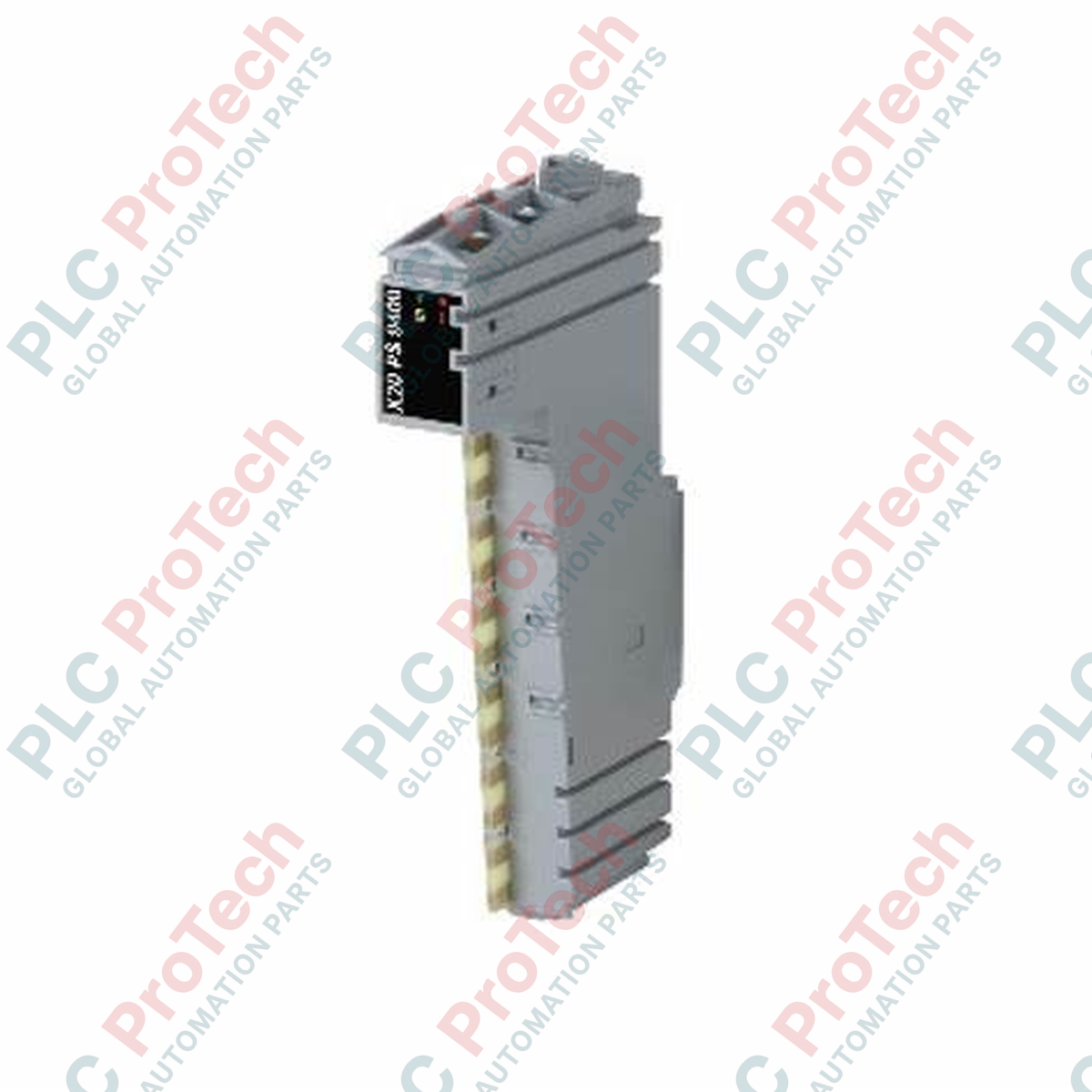
The B&R X20DOF322 (X20DOF322) is a high-density 16-channel digital output module engineered for seamless integration into the modular B&R X20 control platform. Implemented globally across high-volume automated manufacturing environments, automated material handling hubs, and pharmaceutical packaging lines, this module manages discrete actuator networks. By controlling pilot valves, small solenoids, interposing relays, and status indicators directly, the unit enables fast switching speeds and microsecond-level response times, minimizing processing delays and eliminating costly field hardware faults.
Circuit Architecture and Load Protection
This digital module provides 16 transistor-based source (PNP) outputs arranged in a compact 1-wire connection layout to maximize channel density per slot. The module incorporates integrated output protection circuitry, protecting internal solid-state components from downstream overload currents, voltage spikes, and short circuits. This onboard diagnostics layer isolates electrical faults directly to the affected field channel, preventing widespread backplane faults and protecting the upstream controller from localized electrical failures.
Technical Performance Matrix
| Specification Parameter |
Technical Data |
| Model |
X20DOF322 |
| Brand |
B&R Automation |
| Origin |
Austria |
| Output Channels |
16 discrete outputs |
| Output Configuration |
Source switching (PNP layout) |
| Wiring Infrastructure |
1-wire connection design |
| Integrated Safeguards |
Short-circuit, overload, and thermal shutdown protection |
| Operating Temperature Range |
0 to 55 deg C (Standard horizontal mounting) |
| Storage Temperature Range |
-25 to 85 deg C |
| Module Width |
12.5 mm |
| Weight |
0.08 kg (Net) / 2.0 kg (Shipping gross) |
Engineering Diagnostics and FAQs
What are the primary troubleshooting steps if an output channel stops switching?
Verify the status LEDs on the front faceplate of the X20DOF322 module. If the channel indicator is blinking or turned off despite active logic signals in Automation Studio, an overload or short-circuit condition has occurred on that field circuit. Disconnect the field wire, clear the mechanical short at the actuator, and cycle the module power to reset the integrated electronic fuse.
Can the 1-wire connection configuration support inductive loads without external flyback diodes?
Yes. The module includes built-in protective clamping circuits to suppress inductive inductive voltage spikes. However, for high-frequency switching applications or large inductive coils exceeding standard ratings, adding an external flyback diode directly across the load terminal is highly recommended to minimize localized electrical noise.
Is it possible to bridge multiple outputs together to increase the total current capacity?
No. Paralleling outputs on the X20DOF322 to drive heavier loads is not permitted by design. If a high-current load exceeds the individual channel limits, utilize a single digital output channel from this module to switch an external interposing relay or contactor rated for the target load.
Field Commissioning and Terminal Guidelines
-
Common Ground Return Paths: Since this module utilizes a 1-wire connection configuration, all 16 channels share a common ground connection via the terminal block rail or a separate potential distribution module. Ensure that the 0 VDC return path from all field devices connects back to the exact same potential rail as the module supply to prevent floating ground offsets.
-
DC Power Cable Routing: Run all 24 VDC discrete output lines completely separate from high-voltage AC power paths, motor starters, and variable frequency drive (VFD) power cables. Maintain a minimum clearance of 150 mm within cable trays to eliminate capacitive noise coupling, which can cause erratic field sensor switching.
-
Mechanical Terminal Block Engagement: Prior to sliding the X20DOF322 electronic component into the pre-wired X20 terminal block base, verify that all screw or cage-clamp connections are torqued properly. Inspect the gold-plated bus fingers for any dirt or alignment issues to establish solid contact with the internal backplane bus.