BECKHOFF

Beckhoff C9900-E771 Control Panel Accessory Push-button Extension

SKU C9900-E771

In stock
  • 12-month warranty
  • Free returns within 30 days
  • Manufacturer: BECKHOFF
  • Product No.: C9900-E771
  • Origin Germany
  • Product Type: HMI and Control Panel Accessories
  • Payment: T/T, Western Union
  • Weight: 0.5 kg
  • Dimensions: drawings with dimensions of the push-button e x tensions as AutoCAD DXF file
  • Shipping port: Xiamen
  • Warranty: 12 months

Tags

Quantity

Product Description

Description

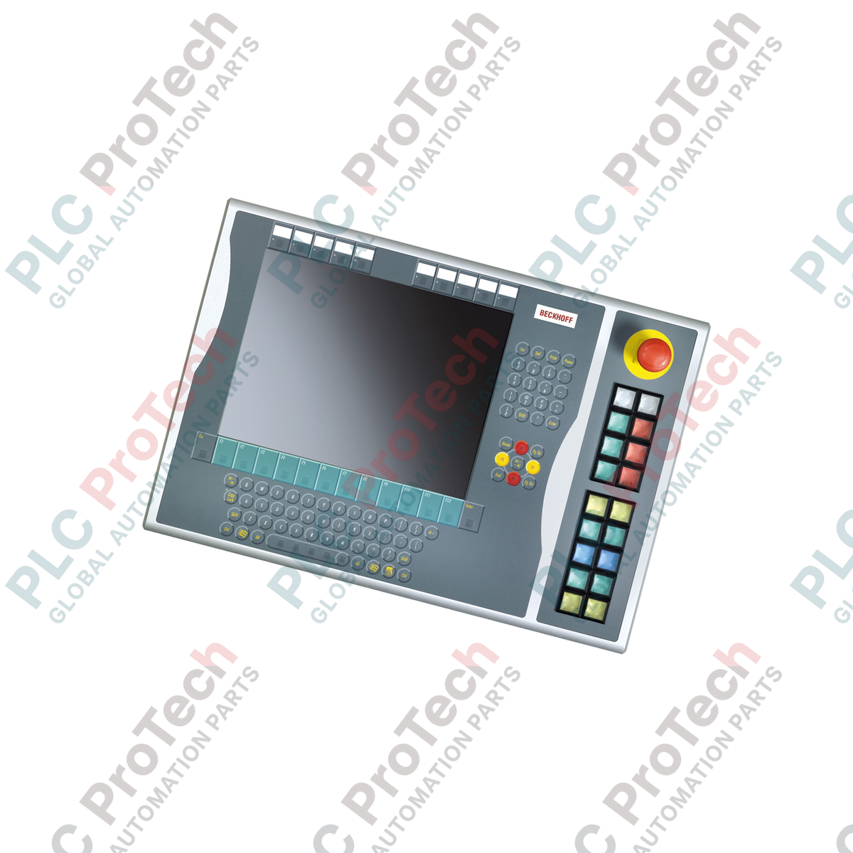
Optimized for right-hand integration on 15-inch display layouts, the Beckhoff C9900-E771 provides robust tactile operator input for legacy CP6x32-00xx and CP7x32-00xx control platforms. Designed for demanding HMI environments, this industrial push-button extension complements host panels without integrated keyboards by adding physical buttons, safety-critical emergency stops, and visual feedback lamps. The unit supports dual-channel signal architecture, combining digital bus transmission (via CP-Link or USB) with direct-wire terminal connections to guarantee system interoperability and fail-safe hardware control.

Features

  • Right-Side Mounting: Engineered specifically to match the physical chassis alignment of 15-inch host panel housings.
  • 18 Illuminated Push-buttons: Equipped with industrial-grade Siemens Signum square keys (30 x 30 mm) featuring built-in signal lamps.
  • Integrated Emergency Stop: Features one heavy-duty Siemens Signum emergency stop button designed for direct hardware wiring.
  • Customizable Labeling: Clear push-button caps permit the insertion of individual custom text or symbol labels for site-specific functions.
  • Dual-Signal Pathways: Every push-button is configured with one normally-open (NO) contact mapped to USB/CP-Link and a second independent NO contact wired directly to a terminal block.
  • Bus-Driven Feedback: Status and signal lamps are mapped and controlled solely through the host CP-Link or USB interface.

Applications

  • Legacy Machinery Retrofits: Direct physical integration with active CP6x32 and CP7x32 operator panels.
  • Process Safety Interfaces: Deployments requiring physical, hardwired emergency-stop circuits adjacent to the software display.
  • Automotive and Assembly Lines: Environments where gloved operators require high-tactility feedback over standard touchscreens.

Technical Specifications

Parameter Specification Value
Manufacturer Beckhoff Automation
Model Reference C9900-E771
Device Type Push-button extension
Host Panel Compatibility CP6x32-00xx, CP7x32-00xx (15-inch displays without keyboard)
Mounting Location Right side of host chassis
Push-Button Element 18 x Siemens Signum square, 30 x 30 mm
Emergency Stop Element 1 x Siemens Signum, direct-wire design
Contact Configuration Normally-Open (NO) x 2 per button (1 x bus, 1 x physical terminal)
Transmission Standard CP-Link or USB (for push-button digital signals and lamp drivers)
Lifecycle Phase Service Phase (Legacy support and spare part availability)
Country of Origin Germany
Shipping Weight 5.00 kg (Estimated)

Connections and Interfaces

Connection Node / Port Functional Assignment
CP-Link / USB Bus Connection Transmits Contact 1 state of all 18 buttons and powers internal status lamps.
Internal Terminal Strip Exposes Contact 2 (Normally Open) for direct electrical wiring to PLC input cards.
Emergency Stop Terminals Dedicated hardwire connection block directly feeding the active-safe E-Stop contacts.

Alternative Models & Compatibility

The C9900-E771 is specifically tailored to complement the dimensional aspect ratio and screw alignments of 15-inch host housings (CP6x32 and CP7x32). While electrically compatible with USB and CP-Link variants across other chassis lines, it cannot be physically mounted to 12-inch or 19-inch panels due to frame height variances. Ensure your physical configuration aligns with the correct target display sizes prior to procurement.

Application Pitfalls & Engineering Notes

Note that status lamps are powered and mapped solely through the CP-Link or USB communication line. In the event of a bus loss, lamp states will fail to update. For safety-critical status loops, the second NO hardware contact on the terminal block should be used to run a physical loopback to an isolated PLC input card, ensuring logic verification independent of the display link.

Commissioning & Wiring Tips

When wiring the direct-access terminal row, use a shielded control cable if routing paths are adjacent to variable frequency drives (VFDs) or three-phase power lines. Connect the cable shield to the cabinet grounding bar. This suppresses transient noise that can trigger false contact state transitions on standard 24V PLC input lines.

Installation Guidelines

CRITICAL WARNING

De-energize the host control panel and any associated 24V DC terminal power lines before physically coupling this expansion unit. Failure to fully discharge system voltage prior to interface connection risks damaging USB controller logic boards and causing terminal short-circuits.

1

Align the expansion bracket of the C9900-E771 with the right-hand mounting track of the host 15-inch control panel.

2

Secure the unit physically using the supplied mounting bolts, ensuring correct torque limits to preserve IP rating integrity.

3

Wire the emergency stop contact block directly into your hardwired safety-monitoring loop (e.g., safety relay or safety PLC).

4

Connect the internal terminal block wiring to the PLC's local digital inputs, if using secondary contact loopbacks.

5

Attach the internal USB or CP-Link connector cable to the designated port on the host computer board, then restore power to test lamp cycles.

Shipping & Returns

Global Express Shipping

  • Standard Delivery: 4–6 business days via DHL, FedEx, and UPS.
  • Express Dispatch: Same-day dispatch for in-stock orders placed before 2:00 PM (GMT+8).
  • Worldwide Coverage: Serving over 150 countries.

Returns & Warranty

  • 30-Day Guarantee: Returns accepted for in-stock products in original, factory-sealed packaging.
  • 12-Month Warranty: Every industrial component is backed by our technical warranty.
FAQ
Can I mount the C9900-E771 on the left side of my control panel?
No. The mechanical mounting brackets, frame offset, and wiring path design of the C9900-E771 are configured strictly for right-side installation on compatible 15-inch Beckhoff panels.
How are the status lamps on the extension controlled?
The integrated status lamps are driven digitally via the host's USB or CP-Link interface. They cannot be directly illuminated using the secondary physical terminal strip.
Is the emergency stop button safety-bus compatible?
Yes, but it must be wired directly. The emergency stop is designed for hardwired integration into your physical safety loop or local safety-monitoring relay (such as TwinSAFE), ensuring it operates independently of standard HMI runtime software.
What is the function of the dual normally-open (NO) contacts?
The dual-contact layout allows for redundancy or split tasks. The first contact state is transmitted digitally via CP-Link/USB to your control application, while the second contact is accessible via the hardware terminal block for legacy direct wiring to traditional PLC input cards.
Reviews

C9900-E771

Stock & lead time on request

Call
1 of 1

Beckhoff C9900-E771 Control Panel Accessory Push-button Extension

Only 10 item(s) left in stock
  • Manufacturer: BECKHOFF

  • Product No.: C9900-E771

  • Country of origin:Germany

  • Product Type: HMI and Control Panel Accessories

  • Payment: T/T, Western Union

  • Weight: 500g

  • Dimensions: drawings with dimensions of the push-button e x tensions as AutoCAD DXF file

  • Shipping port: Xiamen

  • Warranty: 12 months

Quantity
View full details

Description

Optimized for right-hand integration on 15-inch display layouts, the Beckhoff C9900-E771 provides robust tactile operator input for legacy CP6x32-00xx and CP7x32-00xx control platforms. Designed for demanding HMI environments, this industrial push-button extension complements host panels without integrated keyboards by adding physical buttons, safety-critical emergency stops, and visual feedback lamps. The unit supports dual-channel signal architecture, combining digital bus transmission (via CP-Link or USB) with direct-wire terminal connections to guarantee system interoperability and fail-safe hardware control.

Features

  • Right-Side Mounting: Engineered specifically to match the physical chassis alignment of 15-inch host panel housings.
  • 18 Illuminated Push-buttons: Equipped with industrial-grade Siemens Signum square keys (30 x 30 mm) featuring built-in signal lamps.
  • Integrated Emergency Stop: Features one heavy-duty Siemens Signum emergency stop button designed for direct hardware wiring.
  • Customizable Labeling: Clear push-button caps permit the insertion of individual custom text or symbol labels for site-specific functions.
  • Dual-Signal Pathways: Every push-button is configured with one normally-open (NO) contact mapped to USB/CP-Link and a second independent NO contact wired directly to a terminal block.
  • Bus-Driven Feedback: Status and signal lamps are mapped and controlled solely through the host CP-Link or USB interface.

Applications

  • Legacy Machinery Retrofits: Direct physical integration with active CP6x32 and CP7x32 operator panels.
  • Process Safety Interfaces: Deployments requiring physical, hardwired emergency-stop circuits adjacent to the software display.
  • Automotive and Assembly Lines: Environments where gloved operators require high-tactility feedback over standard touchscreens.

Technical Specifications

Parameter Specification Value
Manufacturer Beckhoff Automation
Model Reference C9900-E771
Device Type Push-button extension
Host Panel Compatibility CP6x32-00xx, CP7x32-00xx (15-inch displays without keyboard)
Mounting Location Right side of host chassis
Push-Button Element 18 x Siemens Signum square, 30 x 30 mm
Emergency Stop Element 1 x Siemens Signum, direct-wire design
Contact Configuration Normally-Open (NO) x 2 per button (1 x bus, 1 x physical terminal)
Transmission Standard CP-Link or USB (for push-button digital signals and lamp drivers)
Lifecycle Phase Service Phase (Legacy support and spare part availability)
Country of Origin Germany
Shipping Weight 5.00 kg (Estimated)

Connections and Interfaces

Connection Node / Port Functional Assignment
CP-Link / USB Bus Connection Transmits Contact 1 state of all 18 buttons and powers internal status lamps.
Internal Terminal Strip Exposes Contact 2 (Normally Open) for direct electrical wiring to PLC input cards.
Emergency Stop Terminals Dedicated hardwire connection block directly feeding the active-safe E-Stop contacts.

Alternative Models & Compatibility

The C9900-E771 is specifically tailored to complement the dimensional aspect ratio and screw alignments of 15-inch host housings (CP6x32 and CP7x32). While electrically compatible with USB and CP-Link variants across other chassis lines, it cannot be physically mounted to 12-inch or 19-inch panels due to frame height variances. Ensure your physical configuration aligns with the correct target display sizes prior to procurement.

Application Pitfalls & Engineering Notes

Note that status lamps are powered and mapped solely through the CP-Link or USB communication line. In the event of a bus loss, lamp states will fail to update. For safety-critical status loops, the second NO hardware contact on the terminal block should be used to run a physical loopback to an isolated PLC input card, ensuring logic verification independent of the display link.

Commissioning & Wiring Tips

When wiring the direct-access terminal row, use a shielded control cable if routing paths are adjacent to variable frequency drives (VFDs) or three-phase power lines. Connect the cable shield to the cabinet grounding bar. This suppresses transient noise that can trigger false contact state transitions on standard 24V PLC input lines.

Installation Guidelines

CRITICAL WARNING

De-energize the host control panel and any associated 24V DC terminal power lines before physically coupling this expansion unit. Failure to fully discharge system voltage prior to interface connection risks damaging USB controller logic boards and causing terminal short-circuits.

1

Align the expansion bracket of the C9900-E771 with the right-hand mounting track of the host 15-inch control panel.

2

Secure the unit physically using the supplied mounting bolts, ensuring correct torque limits to preserve IP rating integrity.

3

Wire the emergency stop contact block directly into your hardwired safety-monitoring loop (e.g., safety relay or safety PLC).

4

Connect the internal terminal block wiring to the PLC's local digital inputs, if using secondary contact loopbacks.

5

Attach the internal USB or CP-Link connector cable to the designated port on the host computer board, then restore power to test lamp cycles.

Can I mount the C9900-E771 on the left side of my control panel?

No. The mechanical mounting brackets, frame offset, and wiring path design of the C9900-E771 are configured strictly for right-side installation on compatible 15-inch Beckhoff panels.

How are the status lamps on the extension controlled?

The integrated status lamps are driven digitally via the host's USB or CP-Link interface. They cannot be directly illuminated using the secondary physical terminal strip.

Is the emergency stop button safety-bus compatible?

Yes, but it must be wired directly. The emergency stop is designed for hardwired integration into your physical safety loop or local safety-monitoring relay (such as TwinSAFE), ensuring it operates independently of standard HMI runtime software.

What is the function of the dual normally-open (NO) contacts?

The dual-contact layout allows for redundancy or split tasks. The first contact state is transmitted digitally via CP-Link/USB to your control application, while the second contact is accessible via the hardware terminal block for legacy direct wiring to traditional PLC input cards.

Global Express Shipping

  • Standard Delivery: 4-6 Business Days via DHL, FedEx, and UPS.
  • Express Dispatch: Same-day dispatch for in-stock orders placed before 2:00 PM (GMT+8).
  • Worldwide Coverage: Serving over 150 countries, including rapid delivery to Saudi Arabia and UAE.

Returns & Warranty

  • 30-Day Guarantee: Returns accepted for in-stock products in original, factory-sealed packaging.
  • 12-Month Warranty: Every industrial component is backed by our professional technical warranty.

Orders are processed and delivered Monday-Friday (excluding public holidays).


For full eligibility, restocking fees, and international return details, please view our official Refund & Return Policy .

TECHNICAL SPECIFICATIONS

Country of origin
Germany

Recently Viewed Products

Technical knowledge

Implementing 3-Switch XOR Ladder Logic with Internal Bit

Implement a 3-SPST switch XOR light circuit in LogixPro or RSLogix 500 using an internal relay bit. Includes truth tables, boolean equations, and verified.

Building a Modbus RTU Network with CompactLogix and DeltaV

Integrate Allen-Bradley CompactLogix, Caterpillar ATS, and generators into DeltaV DCS over Modbus RTU. Covers ProSoft MVI69-MCM, Miille DIN266 gateways.

ONS Instruction Not Energizing OTE in Studio 5000 Ladder Logic

ONS instruction fires but the OTE coil never latches in Studio 5000 because the one-shot is only true for one scan. Use OTL/OTU or seal-in logic instead.

Kinetix 5500 EtherNet/IP Network Switch Requirements and Topology

Configure Allen-Bradley Kinetix 5500 servo drives on EtherNet/IP. Covers CIP Sync, IEEE 1588 V2 timing, Stratix selection, DLR topology, and HMI.

Moving Average Filtering in DCS and PLC Analog Control

A moving-average filter is the sliding-window smoother most instrument engineers drop into DCS and PLC analog paths. Here is how the window works, how N and sample time set lag, and when a...

GE Mark VI Function Blocks for Gas Turbine Control Logic

On Frame 5–9 gas turbines, GE Mark VI and Mark VIe run control as function-block application software. This article maps process, protection, and sequencing functions—and what Toolbox ST access...