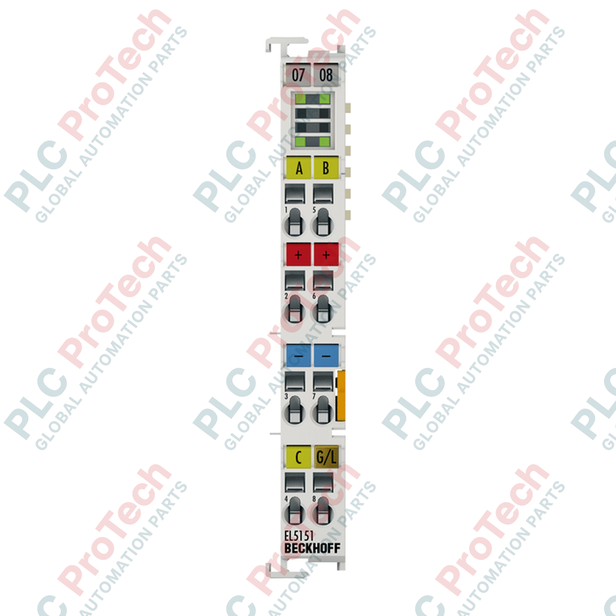
Processing 24 V DC encoder signals directly within the EtherCAT Terminal system, the Beckhoff EL5151 enables precise position and frequency measurement for industrial motion control applications. This module acts as an interface for the direct connection of incremental encoders with 24 V outputs, transmitting the counter state to the higher-level controller via the E-bus.
Key Features
-
Single-Channel Interface: Supports connection of A, B, and C encoder signals.
-
Flexible Counter Depth: Switchable 16-bit and 32-bit counter options to match application requirements.
-
High-Speed Processing: Maximum input frequency of 400,000 increments per second with 4-fold evaluation.
-
Integrated Latch/Gate: Dedicated 24 V DC input for hardware-triggered position latching or counter gating.
-
Microincrement Resolution: High-resolution 1/256 bit microincrements calculation for precise velocity control.
-
E-Bus Powered: Low-power design drawing typically 130 mA from the E-bus.
Industrial Applications
- Closed-loop positioning systems in packaging and assembly machinery.
- Conveyor belt speed synchronization and material tracking.
- Rotary table indexing and angular displacement measurement.
- Integration of 24 V HTL encoders into high-speed EtherCAT networks.
Technical Specifications
| Parameter |
Value |
| Manufacturer |
Beckhoff |
| Model Number |
EL5151 |
| Number of Channels |
1 |
| Encoder Connection |
A, B, C, gate/latch input 24 V DC, 24 V / 0 V |
| Sensor Inputs |
1 |
| Encoder Operating Voltage |
24 V DC |
| Counter |
1 x 16/32 bit (switchable) |
| Input Frequency |
Max. 400,000 increments/s (with 4-fold evaluation) |
| Quadrature Decoder |
4-fold evaluation |
| Input Signal |
24 V DC |
| Supply Voltage |
24 V DC (-15% / +20%) |
| Nominal Voltage |
24 V DC at power contact |
| Resolution |
1/256 bit microincrements |
| Current Consumption E-bus |
Typ. 130 mA |
| Operating Temperature |
-25 to +60 degC |
| Storage Temperature |
-40 to +85 degC |
| Relative Humidity |
95%, non-condensing |
| Dimensions (H x W x D) |
Approx. 100 mm x 15 mm x 70 mm |
| Shipping Weight (Calculated) |
1.5 kg (including protective packaging) |
Connections and Interfaces
| Terminal Connection |
Signal Assignment |
| Input A |
Encoder Signal A (24 V DC) |
| Input B |
Encoder Signal B (24 V DC) |
| Input C |
Encoder Zero Pulse / Latch Signal C (24 V DC) |
| Gate/Latch |
External Gate or Latch Input (24 V DC) |
| 24 V / 0 V |
Power supply points for encoder sensor |
Alternative Models & Compatibility
The EL5151 is designed specifically for 24 V HTL (single-ended) encoder signals. If your system utilizes 5 V differential TTL (RS422) signals, you must use the EL5101 or EL5152 instead. Ensure your TwinCAT configuration matches the hardware revision of the terminal to prevent EtherCAT state machine transition errors (such as "SAFEOP to OP failed").
Application Pitfalls & Engineering Notes
When operating near the maximum input frequency of 400 kHz, signal degradation due to cable capacitance is a common failure point. Ensure that the 24 V encoder signals have clean, sharp rising and falling edges. High-frequency noise on the signal lines can cause the quadrature decoder to register false counts, leading to positioning drift.
Commissioning & Wiring Tips
Always use shielded, twisted-pair (STP) cabling for all encoder connections. The cable shield must be grounded at the control cabinet entry point using low-impedance shield clamps. Configure the counter depth (16-bit vs 32-bit) in the TwinCAT System Manager under the CoE (CAN over EtherCAT) online directory to align with your PLC variable mapping.
Installation Guidelines
CRITICAL WARNING
De-energize the entire system before inserting or removing the terminal from the bus assembly. Failure to isolate the 24 V DC power contacts and E-bus supply can result in permanent damage to the internal bus interface and adjacent modules.
1
Mount the terminal onto the standard 35 mm DIN rail (EN 60715) by aligning the guide slot and sliding it firmly until the locking mechanism clicks.
2
Ensure the side-mounted gold E-bus contacts are clean and free of debris before pushing adjacent terminals together.
3
Connect the encoder wires using a suitable screwdriver to release the tension clamps. Insert the stripped wire end and release the clamp to secure the connection.