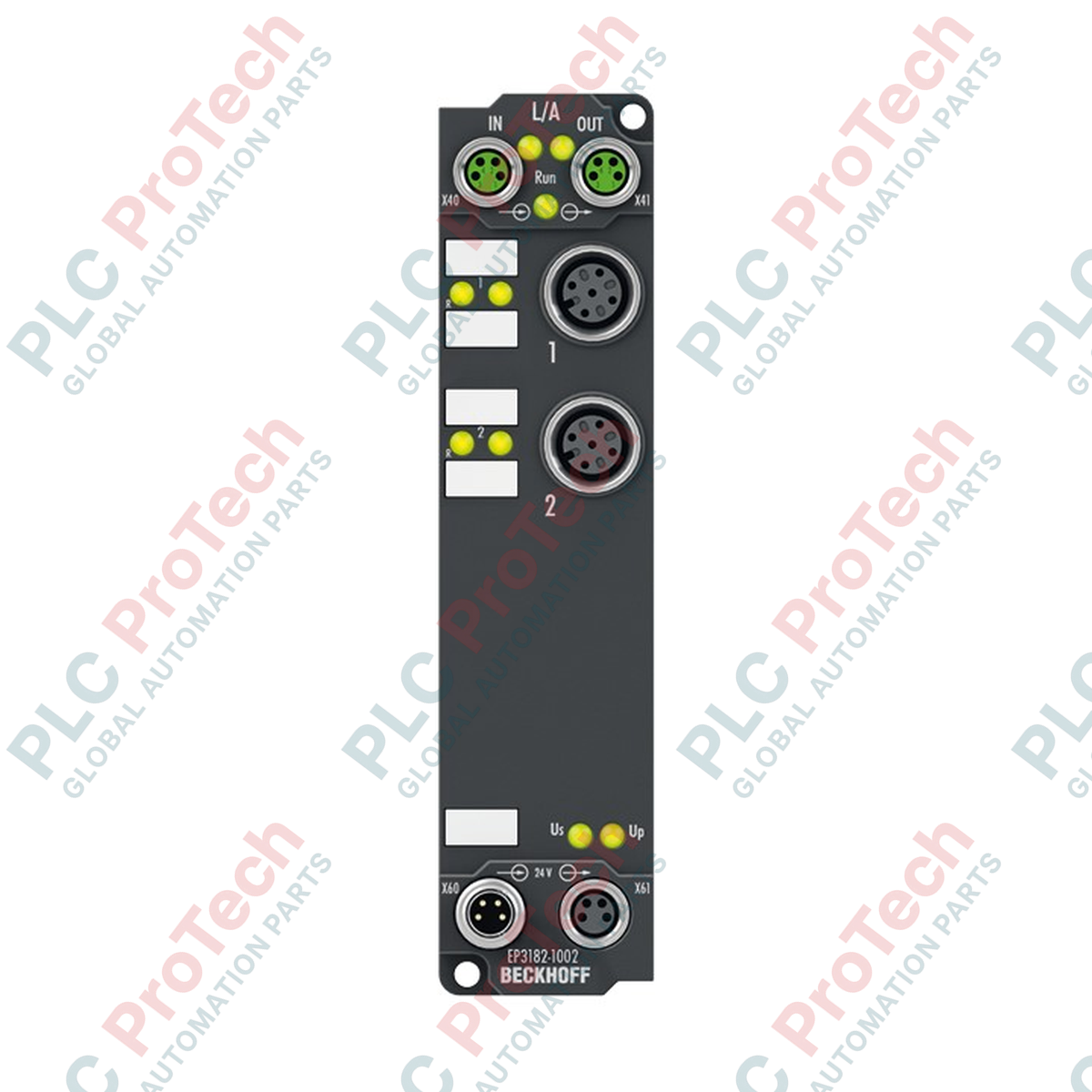
Description
Engineered for direct machine-mount deployments without a control enclosure, the Beckhoff EP3182-1002 EtherCAT Box enables high-precision decentralized data acquisition by processing two parameterizable analog inputs alongside two integrated digital outputs. This module allows individual channel configuration for either -10/0 to +10 V voltage or 0/4 to 20 mA current loops, operating at a high-resolution 16-bit conversion accuracy. Housed in a compact, IP67-rated enclosure, it provides maximum resistance to moisture, dust, and mechanical stress, making it ideal for distributed industrial automation architectures.
Features
-
Multifunctional Analog Channels: 2 single-ended inputs individually configurable for voltage or current signals.
-
Digital Output Channels: 2 digital 24 V DC outputs with short-circuit protection.
-
Robust Fieldbus Connectivity: Dual M8 shielded screw-type connectors for high-speed EtherCAT communication.
-
High Resolution: 16-bit analog-to-digital conversion (including sign) for precise feedback loops.
-
Harsh Environment Protection: Fully sealed IP65, IP66, and IP67 protection ratings.
-
Configurable Filters: Input filter limit frequency of 5 kHz is software-adjustable to reject high-frequency line noise.
Applications
- Decentralized process monitoring (flow, temperature, and pressure transmitters).
- Automotive assembly lines and robotic tool-tip tracking.
- On-machine instrumentation interfacing in material handling and conveyor systems.
- Wind energy systems and outdoor-exposed hydraulic control stations.
Technical Specifications
| Parameter |
Specification Value |
| Manufacturer |
Beckhoff Automation GmbH & Co. KG |
| Model / Article Number |
EP3182-1002 |
| Protocol |
EtherCAT |
| Bus Interface Connection |
2 x M8 socket, shielded, screw-type |
| Number of Inputs |
2 single-ended analog inputs |
| Number of Outputs |
2 digital outputs (24 V DC) |
| Signal Ranges |
-10 to +10 V | 0 to 20 mA | 4 to 20 mA |
| Resolution |
16-bit (including sign) |
| Measurement Uncertainty |
< ±0.3% (relative to full scale value) |
| Conversion Time |
~ 100 us |
| Input Filter Limit Frequency |
5 kHz (configurable) |
| Max. Digital Output Current |
2 mA per channel (short-circuit proof) |
| Internal Resistance |
> 200 kOhm (voltage) | typ. 85 Ohm + diode voltage (current) |
| Current Consumption (from Us) |
120 mA |
| Power Feed Configuration |
1 x M8 male, 4-pin (feed); 1 x M8 female, 4-pin (downstream loop) |
| Electrical Isolation |
Yes (control voltage/fieldbus) |
| IP Rating |
IP65 / IP66 / IP67 (conforms to EN 60529) |
| Operating Temperature |
0 to +55 degC |
| Storage Temperature |
-25 to +85 degC |
| Country of Origin |
Germany |
| Shipping Weight (Calculated) |
2.0 kg (including gross protective packaging) |
| Package Dimensions (Calculated) |
25.0 cm x 15.0 cm x 10.0 cm |
Connections and Interfaces
| Connector / Pin |
Signal Assignment |
Description |
| M12 (Input/Output) Pin 1 |
+24 V DC Sensor Supply (Us) |
Positive auxiliary sensor excitation |
| M12 (Input/Output) Pin 2 |
Analog Input + |
Positive differential signal line (Voltage/Current) |
| M12 (Input/Output) Pin 3 |
GND (Us) |
Reference ground for sensor and digital common |
| M12 (Input/Output) Pin 4 |
Digital Output |
Active channel digital signal (sink/source) |
| M12 (Input/Output) Pin 5 |
Shield / Ground |
Functional earth contact for low-impedance shielding |
Empirical Engineering Insights
Alternative Models & Compatibility
The EP3182-1002 features a combined analog input and low-power digital output mapping structure. If you are replacing older standard EP3174 modules, ensure your TwinCAT system manager configurations are updated to match the specific 16-bit process image of the EP3182-1002. Re-importing the updated Beckhoff ESI (EtherCAT Slave Information) XML file is mandatory to ensure correct channel parameters are visible within the TwinCAT CoE (CoE Online) directory.
Application Pitfalls & Engineering Notes
Be mindful of the 35 V maximum common-mode voltage limit (U_CM) between the analog inputs and the internal module ground. Exceeding this limit will saturate the 16-bit converter or trigger damage. If your field-mounted transmitters are powered from distinct external electrical loops, verify proper potential equalization. Note that digital outputs are limited to 2 mA; they are designed for status indicators or high-impedance logic inputs rather than direct relay coils.
Commissioning & Wiring Tips
Always use fully shielded M12 cabling for the analog sensors to maintain high-frequency noise immunity. Ground loop currents can be prevented by grounding the cable shield at one end only, preferably through the M12 connector casing to the grounded metal body of the EtherCAT Box. Use TwinCAT System Manager's live watch window to verify that the CoE register settings match your physical input wiring (voltage vs. current mode) prior to starting automated machine sequences.
Installation Guidelines
CRITICAL WARNING: Ensure all power lines (control voltage Us and peripheral load voltage Up) are physically de-energized before mounting, wiring, or replacing the EtherCAT box. Failure to do so can cause permanent damage to the internal communications ASIC or corrupt the fieldbus ring topology.
1
Mechanical Mounting: Secure the module directly to the machinery or mounting plate using two M4 bolts. Torque the mounting screws to 1.2 Nm to ensure stable grounding to the machine body.
2
Fieldbus Cable Termination: Attach the incoming and outgoing EtherCAT M8 cables. Hand-tighten the coupling rings, then torque them using an appropriate M8 torque wrench to 0.4 Nm to maintain the IP67-rated moisture seal.
3
I/O & Power Auxiliary Wiring: Terminate the M12 analog sensors and the M8 power distribution cables. Apply 0.6 Nm of torque to the M12 connectors and 0.4 Nm to the power M8 connectors. Unused sockets must be sealed with IP67 protective caps.