Machine-Mount Distributed I/O Overview
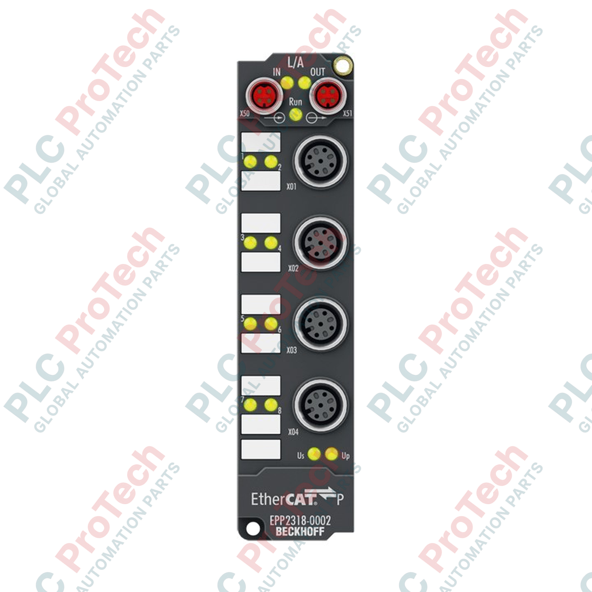
The Beckhoff EPP2318-0002 (EPP2318-0002) is an ultra-rugged, machine-mountable digital I/O module engineered within Beckhoff's high-performance EtherCAT P Box technology framework. Deployed across demanding decentralized industrial ecosystems—such as high-speed robotic articulating arms, heavy-duty automotive welding cells, outdoor material handling lines, and food processing packaging lines—this module bypasses the traditional control cabinet model. By integrating system communication and electrical operating power into a single, unified EtherCAT P cable link, the module dramatically simplifies field topology, reduces mechanical cable track deadweight, and speeds up structural commissioning times.
Mechanical Packaging and Electrical Processing
This IP65/66/67 sealed field module features a balance of four digital inputs and four digital outputs distributed across multi-pin connector ports. The input hardware complies strictly with EN 61131-2 Type 1/3 hardware standards, using a fast 10 µs input filter circuit to record transient sensor states reliably. The output stage features solid-state switches rated for 24 V DC operation (-15% / +20%), capable of sourcing up to 0.5 A of continuous current per channel into ohmic, inductive, or capacitive lamp loads. Built-in protection includes short-circuit proof sensor power limiters and an isolated thermal shutdown architecture to manage downstream wiring faults.
Technical Performance Matrix
| System Parameter |
Functional Specification |
| Model Number |
EPP2318-0002 |
| Brand / Product Family |
Beckhoff Automation / EtherCAT P Box Series |
| Communication Bus |
EtherCAT Protocol Architecture |
| Bus Interface Connectors |
2 x M8 socket, shielded, screw type, P-coded design |
| Channel Configuration |
4 Digital Inputs + 4 Digital Outputs |
| Field Device Ports |
M12 x 1, 5-pin, A-coded interface |
| Input Signal Thresholds |
0 Signal: -3 to +5 V / 1 Signal: 11 to 30 V (6 mA nominal) |
| Input Hardware Filter Time |
10 µs |
| Continuous Output Capacity |
0.5 A per channel (Solid-state switching) |
| Output Dynamic Speeds |
Typical TON: 50 µs / Typical TOFF: 100 µs |
| Sensor Power Safety Limit |
Max. 0.5 A cumulative, fully short-circuit proof |
| Internal Bus Current Draw |
Typically 100 mA drawn from US supply rail |
| Environmental Safety Grade |
IP65 / IP66 / IP67 (Conforms to EN 60529) |
| Thermal Operating Window |
-25 to 60 deg C |
| Net Structural Weight |
approx. 165 g |
| Shipping Gross Weight |
2.0 kg (Enclosed in large-lot industrial packaging) |
Industrial Diagnostics and FAQs
How does the single-cable EtherCAT P technology separate logic power from load power?
EtherCAT P uses specialized P-coded M8 connectors to combine high-speed data transmission with two independent, electrically isolated 24 V DC power supplies in a single cable. The US line powers the internal module electronics and connected sensors, while the UP line supplies power to the output switches and actuators. Because these two potentials share an isolated ground reference, safety interlocks can kill the UP actuator line during an emergency stop condition while keeping the US logic link active for continuous diagnostics.
What are the troubleshooting steps if a channel's output status LED flashes Red?
A red channel status LED indicates an active short-circuit or an overcurrent state exceeding the typical 1.5 A peak threshold. Turn off power to the module and disconnect the M12 field cable from the faulted port. Use a multimeter to check the resistance across the load actuator coil. If a short circuit or failed component is found, repair the field wiring or replace the actuator before re-attaching the A-coded M12 plug to the module.
Does this IP67 box module require a local functional earth grounding conductor?
Yes. To ensure stable operation near high-frequency noise sources like variable frequency drives or plasma power units, attach a heavy-gauge earthing strap from the module's metallic mounting ear directly to the machine's primary structural steel frame. Relying solely on the M8 cable shields can allow high-voltage capacitive noise to build up, which can cause intermittent data dropouts or state corruption.
Field Commissioning and Installation Directives
-
P-Coded M8 Bus Connector Engagement: When running the EtherCAT P network lines, check the internal alignment key of the P-coded M8 male plugs before inserting them into the module's sockets. Hand-tighten the knurled screw-type locking rings completely to ensure the internal rubber O-rings seal against moisture ingress. Never use pliers or over-torque the connectors to avoid cracking the internal molded contact block.
-
A-Coded M12 Field Pin Mapping: Connect external sensors and actuators using standard A-coded 5-pin M12 cable assemblies. Ensure the pin configurations match the module's internal layout: Pin 1 provides sensor power from the US rail, Pin 3 provides the common ground link, and Pin 2/Pin 4 handle individual input/output signaling paths. Cap any unused M12 sockets with watertight industrial sealing plugs to preserve the overall IP67 environment rating.
-
Machine Wall Mounting Constraints: Mount the 165 g compact module block directly to the machine body using rugged M3 or M4 screws passed through the integrated top and bottom mounting holes. The physical installation position is completely variable, but avoid placing the cable entry pathways directly underneath low-point pooling zones where cutting fluids or washdown water collect.