Product Overview
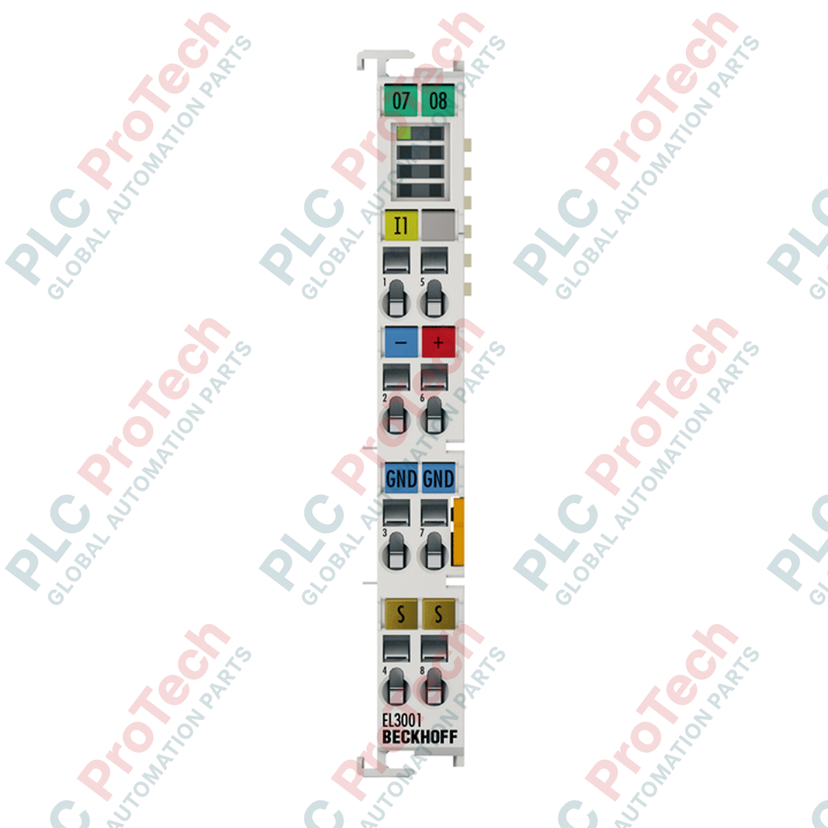
The EL3001 (EL 3001) is a high-performance 1-channel analog input terminal designed for the precise measurement of voltages in the ±10 V range. Utilizing a single-ended signaling technology, this EtherCAT Terminal converts analog field signals into digital data with 12-bit resolution, presented in a 16-bit format to the controller. In heavy-duty industrial sectors such as power plant monitoring, hydraulic press control, and CNC machining, the EL3001 serves as a vital bridge for processing feedback from sensors, potentiometers, and signal transducers. Its compact 12 mm architecture and 500 V electrical isolation ensure that high-precision analog data is maintained even in environments with significant electromagnetic interference, effectively reducing signal noise and preventing system errors.
Technical Configuration
The EL3001 hardware is optimized for flexibility and signal integrity. It features an internal resistance of > 130 kΩ and a standard input filter limit frequency of 1 kHz, which effectively suppresses high-frequency noise. The module offers a conversion time of 0.625 ms in its default multiplex setting, which can be further configured to meet specific application requirements. Advanced firmware features include activatable FIR (Finite Impulse Response) and IIR (Infinite Impulse Response) filters, limit value monitoring, and an integrated overload display within the process data. The terminal is powered directly via the E-bus and requires no manual address or hardware configuration settings, allowing for "plug-and-play" integration into the EtherCAT I/O lineup.
Technical Specifications
| Attribute |
Specification Details |
| Model |
EL3001 |
| Brand |
BECKHOFF |
| Origin |
Germany |
| Number of Inputs |
1 (Single-ended) |
| Signal Voltage |
-10 to +10 V |
| Resolution |
12 bit (16 bit presentation) |
| Conversion Time |
0.625 ms (Default) |
| Measuring Error |
< ±0.3 % (Full scale) |
| Internal Resistance |
> 130 kΩ |
| Current Consumption |
Typ. 130 mA (E-bus) |
| Electrical Isolation |
500 V (E-bus / Field potential) |
| Operating Temperature |
-25 to +60 deg C |
| Dimensions (W x H x D) |
12 mm x 100 mm x 68 mm |
| Protection Rating |
IP20 |
| Weight |
70 g |
| Shipping Weight |
2.0 kg |
| Approvals |
CE, UL, ATEX (II 3 G Ex nA IIC T4 Gc) |
Technical FAQs
Does the EL3001 support differential signal inputs?
No, the EL3001 is specifically designed for single-ended signals where the voltage is measured against a common internal ground. For applications requiring differential inputs to eliminate common-mode noise over long distances, a differential module like the EL3002 should be considered.
How can I reduce signal jitter for high-precision measurements?
The EL3001 features built-in, activatable FIR and IIR filters. These digital filters can be configured via the CoE (CanOverEtherCAT) directory to smooth out fluctuations and adapt the terminal to the specific dynamics of your analog signal source.
What happens if the input voltage exceeds the ±10 V range?
The terminal includes an overload display in the process data. While it can handle a maximum dielectric strength of 30 V without immediate hardware failure, voltages exceeding the ±10 V range will result in saturated process values and the activation of the "Overrange" status bit.
Engineering & Installation Guide
Wiring and Shielding Recommendations:
To ensure a measuring error of less than ±0.3%, use shielded twisted-pair (STP) cabling for all analog signals. The shield should be connected to the functional earth (FE) at the entrance of the control cabinet. For the EL3001, the signal wire should be stripped 8–9 mm and inserted into the spring-loaded terminal using a screwdriver. Ensure the signal ground is stable to prevent "floating" inputs which can lead to erratic readings.
ATEX and Hazardous Area Installation:
When deploying the EL3001 in Zone 2 hazardous areas (marked II 3 G Ex nA IIC T4 Gc), the terminal must be installed in an enclosure providing at least IP54 protection according to EN 60529. Ensure that the power contacts are not disconnected while the circuit is live, as this can cause arcing in explosive atmospheres.
Optimizing Conversion Times:
For high-speed control loops, the conversion time can be adjusted from the default 0.625 ms. However, be aware that faster conversion rates may reduce the effectiveness of internal filtering. For most industrial voltage monitoring tasks, the default multiplex setting provides an optimal balance between speed and signal stability.