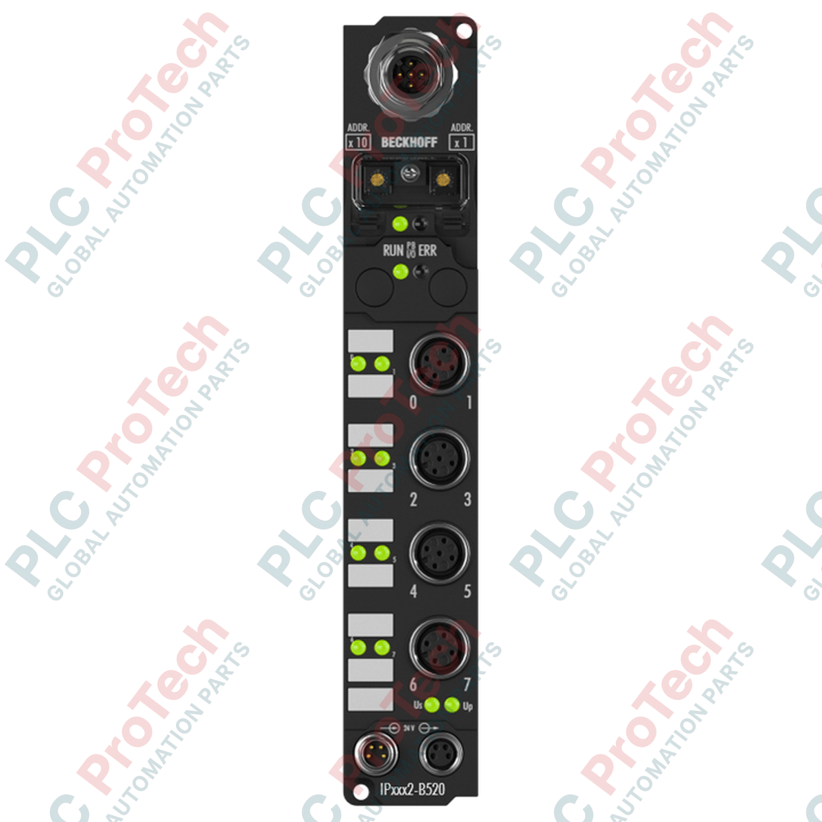
Description
Designed for decentralized automation requirements directly in the field, the IP2002-B520 fieldbus box serves as an integrated, machine-mountable DeviceNet digital output module. This module permits the direct connection of up to eight digital actuators to a DeviceNet controller, bypassing the necessity for protective electrical cabinets. Each of the eight output channels is engineered to handle nominal load voltages of 24 V DC with up to 0.5 A continuous current, making it highly compatible with ohmic, inductive, and lamp loads. Physical connection is achieved via robust, industry-standard M12 screw-type connectors, ensuring signal integrity in harsh, high-vibration manufacturing environments.
Features
- Provides 8 digital outputs rated at 24 V DC, 0.5 A per channel.
- Features integrated DeviceNet interface with automatic transfer rate detection up to 500 kbaud.
- Equipped with individual short-circuit protection on each output channel (typical short-circuit current of 1.5 A).
- Robust polyamide (PA6) housing certified with IP65/66/67 protection class for mounting outside of control cabinets.
- Supports bit strobe, polling, cyclic, and change of state (COS) communication modes.
- Configurable via KS2000 software tool or via explicit messaging from the master controller.
Applications
- Decentralized industrial control systems
- Automotive manufacturing and assembly lines
- Conveyor systems and material handling machinery
- Machine building and tooling systems operating under DeviceNet networks
Technical Specifications
| Manufacturer |
Beckhoff |
| Part Number / Model |
IP2002-B520 |
| Product Series |
IPxxxx (Fieldbus Box) |
| Fieldbus Interface |
DeviceNet (1 x M12 plug, 5-pin) |
| Number of Outputs |
8 |
| Nominal Output Voltage |
24 V DC (-15% / +20%) |
| Max. Output Current |
0.5 A per channel (short-circuit proof) |
| Auxiliary Power Current |
Typically 20 mA per channel |
| Baud Rates Supported |
125 kbaud, 250 kbaud, 500 kbaud (automatic detection) |
| Electrical Isolation |
500 V (Control voltage to fieldbus) |
| Power Feed Connections |
Feed: 1 x M8 male, 4-pin; Downstream: 1 x M8 female, 4-pin |
| Current Consumption |
45 mA + sensor current (max. 0.5 A) |
| Operating Temperature |
0 to +55 degC |
| Storage Temperature |
-25 to +85 degC |
| Vibration / Shock Resistance |
Conforms to EN 60068-2-6 / EN 60068-2-27 |
| EMC Immunity / Emission |
Conforms to EN 61000-6-2 / EN 61000-6-4 |
| Protection Rating |
IP65, IP66, IP67 (conforms to EN 60529) |
| Dimensions (W x H x D) |
30 mm x 175 mm x 26.5 mm |
| Housing Material |
PA6 Polyamide |
| Weight |
2.0 kg (including packaging) |
Connections and Interfaces
| Connection Type |
Interface Style |
Pin Count / Configuration |
| Bus Interface (DeviceNet) |
1 x M12 plug |
5-pin, A-coded |
| Digital Outputs |
8 x M12 screw type |
Individual channel mapping |
| Power Input (Feed) |
1 x M8 male socket |
4-pin |
| Power Output (Downstream) |
1 x M8 female socket |
4-pin |
Installation Guidelines
-
Mounting: Mount the unit directly onto machine frames using the two integrated 3.5 mm diameter fixing holes designed for standard M3 screws.
-
Shielding & Cabling: Use shielded copper cables with a typical sizing of 2 x 2 x 0.25 mm² for all DeviceNet communication runs to guarantee electromagnetic compatibility (EMC).
-
Sealing: To maintain the IP65/66/67 rating, any unused M12 and M8 ports must be securely sealed with appropriate industrial protective caps.
Compliance and Certifications