


Implementing 3-Switch XOR Ladder Logic with Internal Bit
Implement a 3-SPST switch XOR light circuit in LogixPro or RSLogix 500 using an internal relay bit. Includes truth tables, boolean equations, and verified.

Designed to streamline decentralized control architectures, the Beckhoff IP2331-B520 acts as a rugged link between IP67-rated peripheral modules and a standard DeviceNet industrial network. By facilitating remote I/O processing directly at the machine level, this module eliminates the need for protective control cabinets and extensive parallel wiring. It dynamically handles both digital and analog peripheral signals, automatically matching the requirements of connected extension interfaces. Network configuration is easily managed using the KS2000 software tool or via explicit messaging through the host controller.
| Parameter | Specification |
|---|---|
| Manufacturer | Beckhoff |
| Model Number | IP2331-B520 |
| Fieldbus Interface | DeviceNet |
| Bus Connection | 1 x M12 plug, 5-pin |
| Data Transfer Rate | Automatic detection up to 500 kbaud |
| Control Voltage Supply | 24 V DC (-15% / +20%) |
| Load Voltage Supply | Dependent on connected I/O type |
| Internal Box Current Consumption | 45 mA + sensor current (max. 0.5 A) |
| Power Connections | Feed: 1 x M8 male (4-pin); Downstream: 1 x M8 female (4-pin) |
| Isolation Voltage | 500 V (Control voltage / fieldbus) |
| Operating Temperature | 0 to +55 degC |
| Storage Temperature | -25 to +85 degC |
| Protection Rating | IP65 / IP66 / IP67 (conforms to EN 60529) |
| Standards compliance | Vibration EN 60068-2-6, Shock EN 60068-2-27, EMC EN 61000-6-2/4 |
| Approvals | CE, UL |
| Shipping Weight (Calculated) | 2.0 kg |
| Connection Type | Pin Mapping & Assignment |
|---|---|
| DeviceNet M12 Bus Plug (5-pin) | Pin 1: Shield | Pin 2: V+ | Pin 3: V- | Pin 4: CAN_H | Pin 5: CAN_L |
| Power Feed M8 Male (4-pin) | Pin 1: Feed 24 V DC Control | Pin 2: Feed 24 V DC Load | Pin 3: GND Control | Pin 4: GND Load |
| Power Downstream M8 Female (4-pin) | Pin 1: Loop 24 V DC Control | Pin 2: Loop 24 V DC Load | Pin 3: GND Control | Pin 4: GND Load |
The IP2331-B520 offers functional backward compatibility with the earlier legacy IP2330 model series. However, to maintain high-integrity diagnostic communication under DeviceNet, network masters must be updated with the correct Electronic Data Sheet (EDS) matching the B520 firmware revision. System upgrades must verify device configuration files before deployment.
When daisy-chaining power across multiple modules via the M8 connectors, ensure the total loop-through current does not exceed the absolute limit of 4 A. Exceeding this threshold can lead to localized thermal degradation inside the terminal housing and cause unexpected communication drops. Separate isolated power lines should be run for control networks to avoid high-inductance electrical noise feedback on the data bus.
For successful automatic baud-rate determination, at least one node must actively transmit data on the DeviceNet network. Always terminate both far ends of the physical trunk with a 120-ohm resistor. If troubleshooting fieldbus signals, check the integrated status LEDs for common DeviceNet physical layer issues, such as grounding offsets between remote power drops.
Mount the Fieldbus Box onto a clean, flat surface using two M4 bolts, tightening them to a torque of 1.2 Nm to prevent structural strain on the plastic body.
Configure the physical DeviceNet node address using the hardware rotaries or DIP switches prior to powering up the system.
Firmly hand-tighten the M12 DeviceNet and M8 power cables to maintain their environmental IP67 seal integrity; do not use pliers, which can crack the threaded couplings.
Apply control voltage first to verify communications, then turn on the load voltage supply loop to enable peripheral sensors and field actuators.
Global Express Shipping
Returns & Warranty


Manufacturer: BECKHOFF
Product No.: IP2331-B520
Country of origin:Germany
Product Type: Fieldbus Box Modules
Payment: T/T, Western Union
Weight: 500g
Shipping port: Xiamen
Warranty: 12 months
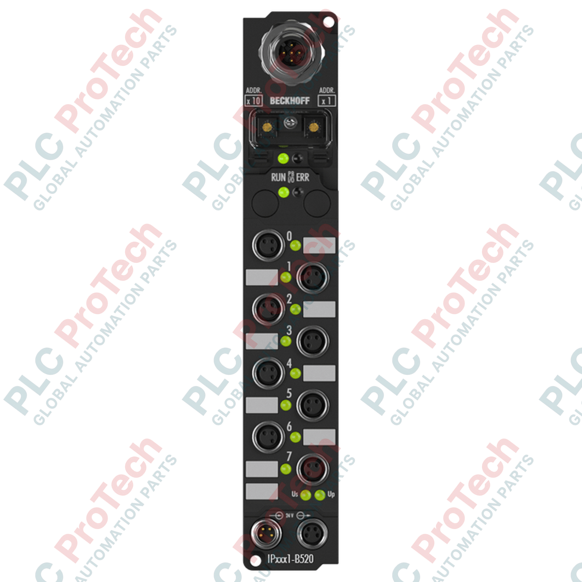
Designed to streamline decentralized control architectures, the Beckhoff IP2331-B520 acts as a rugged link between IP67-rated peripheral modules and a standard DeviceNet industrial network. By facilitating remote I/O processing directly at the machine level, this module eliminates the need for protective control cabinets and extensive parallel wiring. It dynamically handles both digital and analog peripheral signals, automatically matching the requirements of connected extension interfaces. Network configuration is easily managed using the KS2000 software tool or via explicit messaging through the host controller.
| Parameter | Specification |
|---|---|
| Manufacturer | Beckhoff |
| Model Number | IP2331-B520 |
| Fieldbus Interface | DeviceNet |
| Bus Connection | 1 x M12 plug, 5-pin |
| Data Transfer Rate | Automatic detection up to 500 kbaud |
| Control Voltage Supply | 24 V DC (-15% / +20%) |
| Load Voltage Supply | Dependent on connected I/O type |
| Internal Box Current Consumption | 45 mA + sensor current (max. 0.5 A) |
| Power Connections | Feed: 1 x M8 male (4-pin); Downstream: 1 x M8 female (4-pin) |
| Isolation Voltage | 500 V (Control voltage / fieldbus) |
| Operating Temperature | 0 to +55 degC |
| Storage Temperature | -25 to +85 degC |
| Protection Rating | IP65 / IP66 / IP67 (conforms to EN 60529) |
| Standards compliance | Vibration EN 60068-2-6, Shock EN 60068-2-27, EMC EN 61000-6-2/4 |
| Approvals | CE, UL |
| Shipping Weight (Calculated) | 2.0 kg |
| Connection Type | Pin Mapping & Assignment |
|---|---|
| DeviceNet M12 Bus Plug (5-pin) | Pin 1: Shield | Pin 2: V+ | Pin 3: V- | Pin 4: CAN_H | Pin 5: CAN_L |
| Power Feed M8 Male (4-pin) | Pin 1: Feed 24 V DC Control | Pin 2: Feed 24 V DC Load | Pin 3: GND Control | Pin 4: GND Load |
| Power Downstream M8 Female (4-pin) | Pin 1: Loop 24 V DC Control | Pin 2: Loop 24 V DC Load | Pin 3: GND Control | Pin 4: GND Load |
The IP2331-B520 offers functional backward compatibility with the earlier legacy IP2330 model series. However, to maintain high-integrity diagnostic communication under DeviceNet, network masters must be updated with the correct Electronic Data Sheet (EDS) matching the B520 firmware revision. System upgrades must verify device configuration files before deployment.
When daisy-chaining power across multiple modules via the M8 connectors, ensure the total loop-through current does not exceed the absolute limit of 4 A. Exceeding this threshold can lead to localized thermal degradation inside the terminal housing and cause unexpected communication drops. Separate isolated power lines should be run for control networks to avoid high-inductance electrical noise feedback on the data bus.
For successful automatic baud-rate determination, at least one node must actively transmit data on the DeviceNet network. Always terminate both far ends of the physical trunk with a 120-ohm resistor. If troubleshooting fieldbus signals, check the integrated status LEDs for common DeviceNet physical layer issues, such as grounding offsets between remote power drops.
Mount the Fieldbus Box onto a clean, flat surface using two M4 bolts, tightening them to a torque of 1.2 Nm to prevent structural strain on the plastic body.
Configure the physical DeviceNet node address using the hardware rotaries or DIP switches prior to powering up the system.
Firmly hand-tighten the M12 DeviceNet and M8 power cables to maintain their environmental IP67 seal integrity; do not use pliers, which can crack the threaded couplings.
Apply control voltage first to verify communications, then turn on the load voltage supply loop to enable peripheral sensors and field actuators.
Global Express Shipping
Returns & Warranty
Orders are processed and delivered Monday-Friday (excluding public holidays).
For full eligibility, restocking fees, and international return details, please view our official Refund & Return Policy .
| Country of origin |
Germany
|

Implement a 3-SPST switch XOR light circuit in LogixPro or RSLogix 500 using an internal relay bit. Includes truth tables, boolean equations, and verified.

Integrate Allen-Bradley CompactLogix, Caterpillar ATS, and generators into DeltaV DCS over Modbus RTU. Covers ProSoft MVI69-MCM, Miille DIN266 gateways.

ONS instruction fires but the OTE coil never latches in Studio 5000 because the one-shot is only true for one scan. Use OTL/OTU or seal-in logic instead.

Configure Allen-Bradley Kinetix 5500 servo drives on EtherNet/IP. Covers CIP Sync, IEEE 1588 V2 timing, Stratix selection, DLR topology, and HMI.

A moving-average filter is the sliding-window smoother most instrument engineers drop into DCS and PLC analog paths. Here is how the window works, how N and sample time set lag, and when a...

On Frame 5–9 gas turbines, GE Mark VI and Mark VIe run control as function-block application software. This article maps process, protection, and sequencing functions—and what Toolbox ST access...