Process Automation and Manual Override Functionality
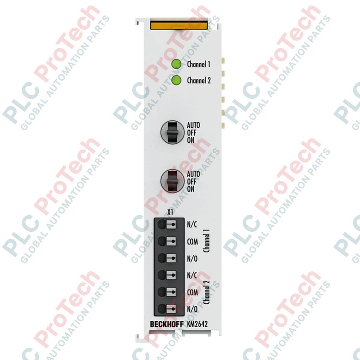
The Beckhoff KM2642 (KM2642) is a high-capacity 2-channel digital output relay terminal module engineered for the modular Beckhoff K-bus I/O system. Deployed across facility environmental installations, critical HVAC plant logic circuits, and automated lighting control grids, this specialized terminal features integrated manual/automatic override switches on the front faceplate. This hardware arrangement permits maintenance engineers to physically force the relay states during field commissioning or emergency override scenarios, enabling direct localized system diagnostics without requiring an active master PLC program run.
Electrical Profile and Contact Dynamics
This Bus Terminal incorporates two independent change-over (SPDT) relays configured to switch alternating current potentials up to a nominal voltage of 230 V AC, with an absolute switching peak threshold of 250 V AC. Constructed using highly durable silver tin oxide ($\text{AgSnO}_2$) contact metallurgy to resist material transfer and arc erosion, each independent channel handles a continuous electrical current rating of up to 6 A. The contact infrastructure accommodates ohmic, inductive, and capacitive lamp loads, sustaining high-inrush starting surges up to 10 A from electronic ballasts while maintaining a minimal operational current consumption of 130 mA from the digital K-bus backbone.
Technical Performance Matrix
| Core Parameter |
Functional Specification |
| Model Number |
KM2642 |
| Brand |
Beckhoff Automation |
| Origin |
Germany |
| Module Classification |
K-Bus Terminal Manual/Automatic Relay Module |
| Output Configuration |
2 x Change-over (SPDT Form C) contact sets |
| Nominal Voltage Ceiling |
230 V AC (Absolute maximum 250 V AC) |
| Continuous Current Capacity |
6 A per independent channel |
| Maximum Switching Power |
1.5 kVA |
| Minimum Required Load |
100 mA at 12 V |
| Ballast Inrush Tolerances |
Max. 10 A starting current peak |
| Contact Composition |
Silver Tin Oxide ($\text{AgSnO}_2$) |
| Process Image Footprint |
2 digital inputs (Feedback) / 2 digital outputs |
| Mechanical Service Life |
Minimum 1 x $10^6$ operations |
| Electrical Service Life |
Minimum 1 x $10^5$ operations (3 A / 250 V AC) |
| K-Bus Logic Current Draw |
Typically 130 mA |
| Operating Temperature |
0 to +55 deg C (Non-condensing) |
| Storage Temperature |
-25 to +85 deg C |
| Ingress Safety Shield |
IP20 Open Type Enclosure |
| Net Assembly Weight |
approx. 110 g |
| Shipping Gross Weight |
3.0 kg (Enclosed in large-lot industrial packaging) |
Industrial Diagnostics and FAQs
How do the manual toggle switches interact with the TwinCAT process image?
The faceplate switches physically route the control signal path. When positioned to "Auto," the relay state is determined by the 2 digital output bits mapped in the TwinCAT process image. When toggled to "Manual (ON/OFF)," the physical contact position changes regardless of controller commands. The module passes 2 digital input bits back to the PLC process image to notify the application code whether the relay is actively energized or de-energized, ensuring full loop monitoring.
What causes premature contact welding on a relay channel rated for 6 A?
Premature contact degradation usually stems from unmitigated inductive or capacitive inrush currents. While the $\text{AgSnO}_2$ material handles continuous resistive loads at 6 A, high-efficiency LED drivers or inductive solenoid coils generate transient starting currents exceeding the 10 A ballast threshold. To extend the module's operating life, install external RC snubbers across AC inductive loads or apply dedicated inrush current limiters.
Is any hardware node addressing required when adding this module to a terminal segment?
No. The KM2642 requires no manual address calculation or physical DIP switch adjustment. The module identifies itself automatically to the upstream bus coupler (such as a BK1120 or BK9000) during initialization, mapping its internal 2-input and 2-output register configuration directly into the K-bus bit stream according to its physical position on the DIN rail stack.
Field Commissioning and Wiring Guidelines
-
Change-Over Terminal Path Allocation: Verify the terminal assignment layout before landing live AC conductors. Because these are true change-over contacts, each channel features a Common (C), Normally Open (NO), and Normally Closed (NC) connection path. Ensure the load line is terminated on the correct pin to prevent inverse operation when switching between automatic and manual modes.
-
Inductive Arc Suppression: When utilizing the terminal to cycle inductive loads—such as raw contactor coils, mechanical brake solenoids, or small single-phase pump motors—always wire an external protective surge suppressor parallel to the load. This dampens back-EMF voltage spikes during contact opening, preventing high-voltage arcing across the silver tin oxide contacts and avoiding systemic electromagnetic noise injection into the K-bus rail.
-
DIN Rail Grounding and Thermal Clearances: Snap the IP20 chassis securely onto standard TS35 DIN rails, ensuring the internal data bus contacts engage smoothly with adjacent slices. Mount the assembly horizontally within a well-ventilated enclosure. Maintain a minimum of 30 mm vertical air clearance above and below the module block to ensure optimal convective cooling across its 0 to +55 deg C operating window.