Product Overview
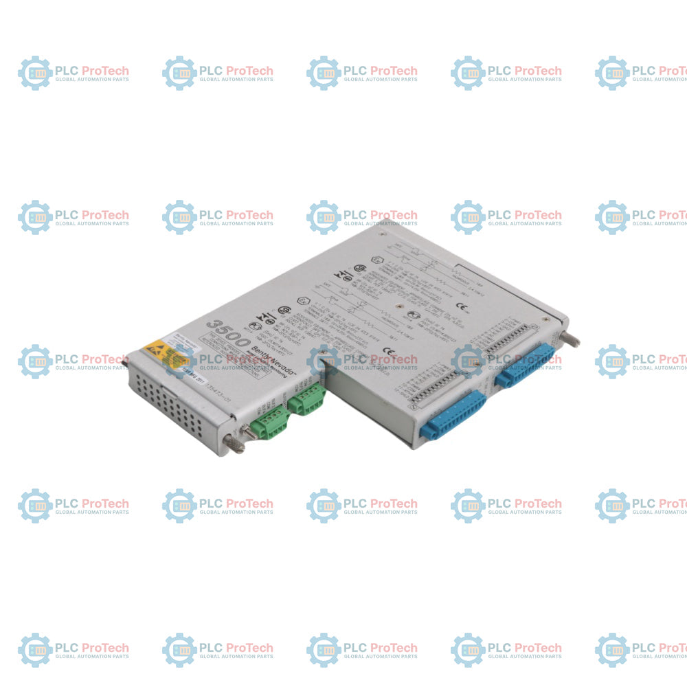
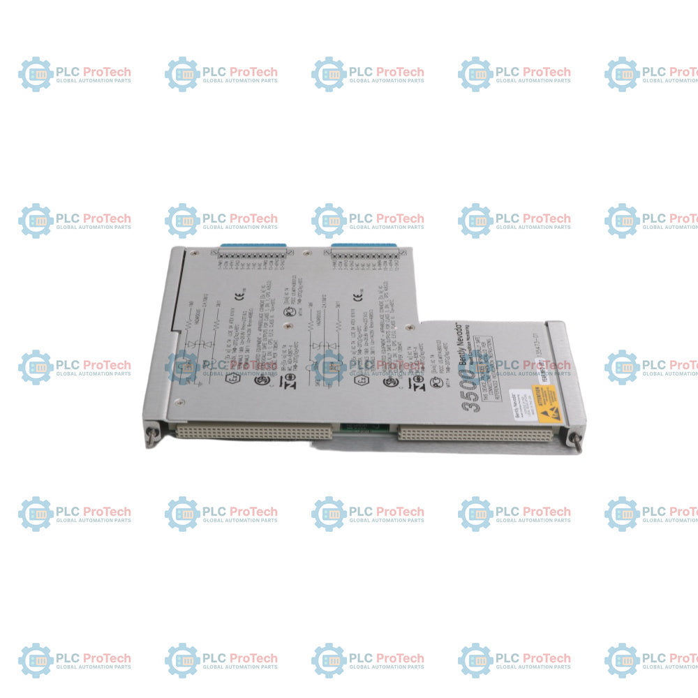
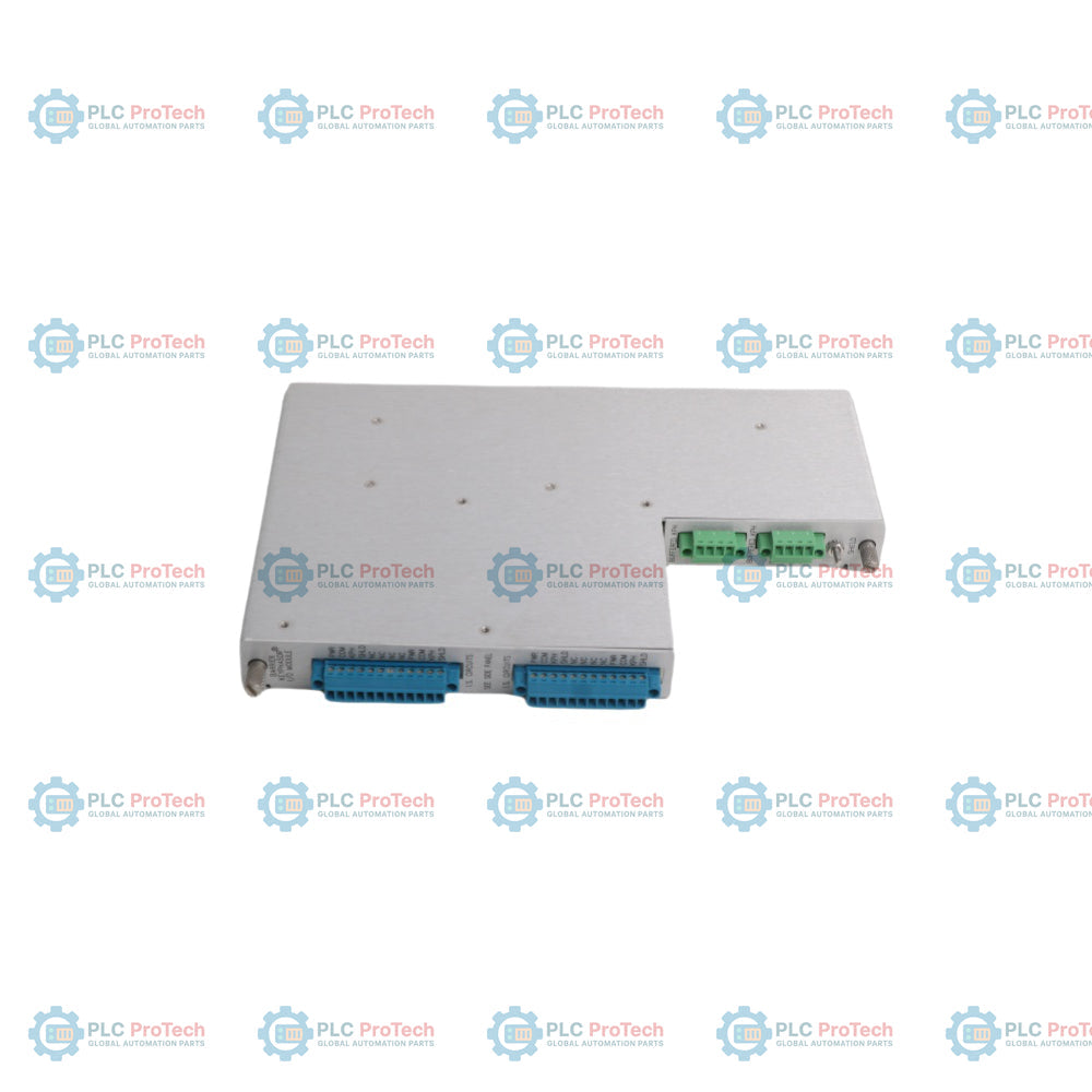
The Bently Nevada 135473-01 is a specialized half-height I/O module designed for the 3500/25 Enhanced Keyphasor system. This specific configuration integrates Internal Barriers and Internal Terminations, providing a hardware-based intrinsic safety interface for transducers located in hazardous areas. The module is engineered to receive and process once-per-turn or multiple-per-turn pulse signals from proximity probes or magnetic pickups, which are essential for calculating machine rotative speed and providing a phase reference for vibration analysis.
The 135473-01 acts as the physical interface within the 3500 rack, ensuring electrical isolation and signal conditioning for critical machinery protection. While the module supports phase measurements, it is optimized for high-accuracy shaft speed monitoring. When utilizing the internal barrier version, the module provides a secure connection point that limits electrical energy dispatched to field sensors, complying with rigorous industrial safety standards for explosive atmospheres.
Technical Configuration
| Attribute |
Specification |
| Model |
135473-01 |
| Brand |
Bently Nevada |
| Product Type |
Keyphasor I/O Module |
| Series |
3500 Series |
| Termination Type |
Internal Terminations |
| Safety Interface |
Internal Barriers (Zener Type) |
| Input Channels |
2 Transducer Signals (Proximity or Magnetic Pickup) |
| Power Consumption |
3.2 Watts typical |
| Input Impedance |
21.8 k ohm minimum |
| Signal Range (Non-Isolated) |
+0.8 V to -21.0 V |
| Magnetic Pickup Min Speed |
> 200 rpm (3.3 Hz) |
| Dimensions (H x W x D) |
241.3 mm x 24.4 mm x 103.1 mm |
| Weight |
0.46 kg (1.01 lbs) |
| Operating Temperature |
0 deg C to +65 deg C (32 deg F to +150 deg F) |
| Storage Temperature |
-40 deg C to +85 deg C (-40 deg F to +185 deg F) |
| Humidity |
95% non-condensing |
Ordering Information
Industrial procurement should focus on the specific part number to ensure compatibility with the 3500/25 monitor configuration.
FAQ
-
Can this module provide isolation for Proximitor applications?
Yes, it is compatible with Proximitor applications but requires an external power supply to provide isolation.
-
What is the primary design intent of the Isolated I/O version?
It was created specifically for magnetic pickup applications where signals are tied in parallel to multiple devices, such as control systems.
-
What happens if input signals exceed the specified range?
Signals exceeding the specified voltage range are limited internally by the module circuitry.
Technical Reference: Wiring, Jumpers, and Specifications
1. CHANNEL WIRING & PIN DEFINITIONS
The 135473-01 is an Internal Termination I/O module with built-in Galvanic Barriers. It features two independent terminal strips for Channel 1 and Channel 2.
A. Proximity Probe Wiring (3-Wire)
For standard eddy current sensors (e.g., 3300 XL series):
-
PWR (-24V): Power output for the Proximitor.
-
COM (GND): Signal common/return.
-
SIG (OUT): Input for the pulse voltage signal.
B. Magnetic Pickup Wiring (Passive 2-Wire)
For self-generating electromagnetic speed sensors:
-
SIG: Connect to sensor positive (+) lead.
-
COM: Connect to sensor negative (-) lead.
-
PWR: Must remain disconnected (Floating).
C. Shielding and IS Grounding
-
SHLD (Shield): Connect field cable shields to this dedicated terminal.
-
IS Earth : This module must be grounded via the 136719-01 Barrier Earth Module to a dedicated Intrinsic Safety ground bus to ensure explosion-proof integrity.
2. HARDWARE JUMPER CONFIGURATIONS
Jumpers are located on the internal circuit board and must be set before installation.
| Transducer Type |
Transducer Power Jumper |
Input Coupling Jumper |
Logical Function |
| Proximity Probe |
INT (Internal) |
DC (Direct Current) |
Provides power; allows DC bias. |
| Magnetic Pickup |
EXT (External/OFF) |
AC (Alternating Current) |
Cuts power; filters DC noise. |
IMPORTANT: Always power down the 3500 rack or remove the Monitor Module before adjusting jumpers to avoid electrical arcing.
3. CORE PERFORMANCE SPECIFICATIONS
-
Channel Capacity: 2 independent input channels.
-
Frequency Range: 1 to 1,200,000 cpm (0.017 Hz to 20 kHz).
-
Input Voltage Range: +5V to -11V (specifically for Barrier I/O).
-
Conditioning Modes:
-
Environmental:
4. HAZARDOUS AREA CERTIFICATIONS
Designed for high-risk environments:
-
North America: Class I, Div 2, Groups A, B, C, D.
-
Europe (ATEX): II 1 G [EEx ia] IIC (Inputs rated for Zone 0).
5. SYSTEM CONFIGURATION SUPPORT
After the physical installation, use the 3500 Rack Configuration Software to verify:
-
Hysteresis Settings: To prevent false triggering on noisy signals.
-
Orientation: Setting the pulse direction (Positive/Negative).
-
Active Channels: Ensuring the software matches the physical jumper settings.
PART 2: TERMINAL DIAGRAMS & SOFTWARE CONFIGURATION
1. TERMINAL BLOCK PINOUT (A/B/C/D)
The 135473-01 uses a specific 4-terminal sequence for each channel. Below is the mapping for connecting your field wiring:
| Terminal |
Label |
Proximity Probe (3-Wire) |
Magnetic Pickup (2-Wire) |
| A |
PWR |
-24 Vdc Power (White) |
NO CONNECTION |
| B |
COM |
Common/GND (Black) |
Signal Negative (-) |
| C |
SIG |
Signal Input (Red) |
Signal Positive (+) |
| D |
SHLD |
Shield/Drain Wire |
Shield/Drain Wire |
2. SOFTWARE CONFIGURATION (3500 RACK CONFIG)
Once the hardware is installed, you must configure the following in the software utility:
A. Threshold Settings
-
Auto Threshold:
-
The system automatically calculates the trigger point at 50% of the signal amplitude.
-
Best for: Standard operating speeds (>120 rpm) with clean, consistent pulses.
-
Manual Threshold:
-
You manually set a fixed voltage (e.g., -8.0 Vdc).
-
Best for: Low-speed start-ups or signals with significant "glitch" or noise.
-
Calculation Tip: Set the threshold to the midpoint between the pulse peak and the baseline signal.
B. Hysteresis (Noise Reduction)
C. Active Edge (Direction)
3. CRITICAL INSTALLATION CHECKLIST
-
Barrier Earth: Ensure the 136719-01 module is installed in the rack. Without this, the 135473-01 cannot properly ground the internal safety barriers.
-
Jumper Audit: Double-check that Channel 1 and Channel 2 jumpers match their respective sensors. A common error is leaving the PWR jumper on INT when using a Magnetic Pickup, which can induce noise or heat.
-
Encoding: Use deg C and Celsius in your technical documentation to avoid the corrupted character issues previously encountered in your CMS.