Description
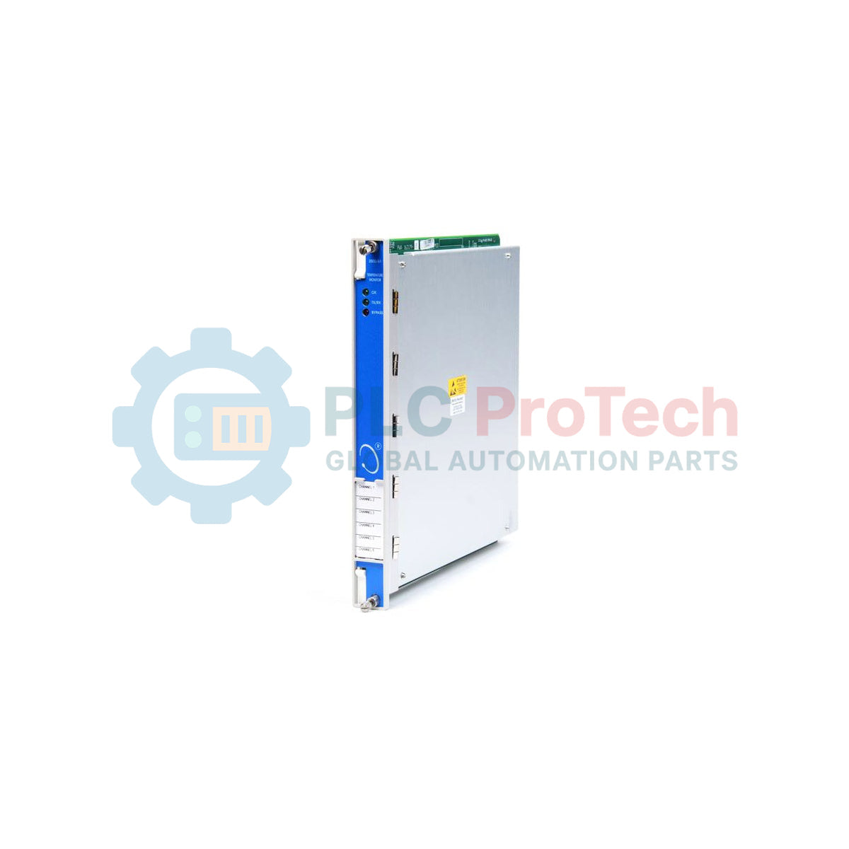
Providing highly reliable thermal sensor integration within industrial machinery protection systems, the Bently Nevada 163179-02 serves as the dedicated RTD/TC Non-Isolated I/O Module with Internal Terminations. Engineered specifically for use with the 3500/60 and 3500/61 Temperature Monitor series, this hardware interface accepts inputs from both Resistive Temperature Detectors (RTD) and Thermocouples (TC). Its internal termination design eliminates the need for external terminal blocks, simplifying control cabinet layouts and reducing field wiring complexity. Each module connects directly to the backplane of the 3500 rack, transmitting digitized temperature data to the main monitor module for real-time safety trips and machinery diagnostics.
Features
-
Direct Sensor Connection: Supports dual-element RTDs and various thermocouple calibrations without external signal conditioning.
-
Internal Terminations: Integrated terminal strips located directly on the card ease point-to-point field wiring.
-
Non-Isolated Architecture: Cost-efficient, space-saving design optimized for installations sharing a common instrumentation ground.
-
Dynamic Hot-Swapping: Minimizes system downtime by allowing rear module replacement while keeping adjacent modules online.
-
Machinery Protection Integration: Communicates seamlessly with the 3500 backplane to trigger automatic emergency trip limits.
Applications
- Radial and thrust bearing temperature monitoring in heavy steam or gas turbines.
- Thermal monitoring of generator stator windings and rotor bearing housings.
- Continuous casing and process gas temperature diagnostics in centrifugal compressors.
- High-capacity electric motor protection in critical petrochemical and mining facilities.
Technical Specifications Table
| Parameter |
Specification Values |
| Manufacturer |
Bently Nevada (Baker Hughes) |
| Part Number / SKU |
163179-02 (Component of 3500/60) |
| Module Type |
RTD/TC Non-Isolated I/O Module |
| Termination Style |
Internal Terminations (Screw clamp terminals) |
| Compatible Monitors |
3500/60 and 3500/61 Temperature Monitors |
| Thermocouple Types |
Type J, K, T, E (with cold-junction compensation) |
| RTD Types |
100 ohm Platinum (3-wire and 4-wire configurations) |
| Operating Temperature |
-30 degC to +65 degC |
| Country of Origin |
United States |
| Shipping Weight (Calculated) |
3.0 kg |
Connections and Interfaces
The rear terminal strip provides hardwired connections for up to six separate temperature channels. Use shielded twisted-pair cabling for all RTD and TC inputs to maintain noise immunity.
| Terminal Label |
RTD Mode Connection |
Thermocouple Mode Connection |
| A |
Source / Lead Compensation |
No Connection (Open) |
| B |
Signal (+) Return |
Positive (+) Leg |
| C |
Common (-) Return |
Negative (-) Leg |
| SHIELD |
Instrument Ground Shield |
Instrument Ground Shield |
Empirical Engineering Insights
Alternative Models & Compatibility
The 163179-02 non-isolated module features integrated internal termination blocks. If replacing older external termination setups (such as the 133900-01 board), you must convert your wiring topology to land directly on this rear module. Ensure that the main front-facing 3500/60 or 3500/61 processor card runs compatible firmware to correctly recognize the non-isolated parameter set.
Application Pitfalls & Engineering Notes
Because this module is non-isolated, all input grounds share a common reference potential inside the 3500 rack. Avoid using non-isolated sensors in electrically noisy settings or in plants experiencing ground grid variance, as this can lead to phantom temperature spikes, high-level noise on signal loops, or false alarm triggers. If sensors are ungrounded at the field junction, always tie the cable shields directly to the chassis ground terminal of this I/O module.
Commissioning & Wiring Tips
For installations utilizing thermocouples, allow the internal cold junction compensation (CJC) circuit to thermally stabilize for 15 to 20 minutes after cabinet power-up before taking baseline commissioning readings. Always route instrument-level RTD/TC wiring through isolated cable trays away from high-voltage motor feeds to mitigate electromagnetic interference.
Installation Guidelines
CRITICAL WARNING:
De-energize the entire 3500 chassis and isolate all auxiliary trip loops before extracting or installing rear I/O cards. Failure to bypass active protection outputs could result in an accidental plant shut down or equipment trip.
1
Power down the rack or switch the front-panel keyswitch to "Program Mode" to inhibit auto-trips.
2
Align the 163179-02 card with the designated guide rails on the rear chassis slot corresponding to the monitor module.
3
Slide the module firmly forward into the backplane connectors until the mounting screws line up with the rack frame.
4
Tighten the retaining screws to ground the module housing properly. Secure all sensor channels onto the internal screw terminals.